How they work, how they go wrong, and how they can be improved.
An Historical Point.
The Jaguar V12 was always intended to be fuel injected - the carburetor setup with which it was launched was hastily cobbled together when the Brico Directors suddenly scrapped the promising Brico EFI system at the eleventh hour. Of course, Jaguar maintained that there was always a carburetor development in the background 'just in case' but there must have been great disappointment at being forced into using what was clearly the second best option. As for the Brico Board of Directors, perhaps it wasn't so much cold feet as realisation that their system had so much in common with the established Bosch D Jetronic that a serious commercial and legal battle was almost inevitable. Little Brico, although part of the AE group, could hardly have taken on Bosch with any hope of winning. Of course, we will never know the real reason but I suggest this as a likely explanation.
At this point the obvious step was taken to develop the Bosch D Jetronic system in a version suited to the V12. Lucas undertook this work and the system was successfully introduced in 1975 and this is all chronicled elsewhere on the AJ6 Engineering website. It is recommended reading for those who wish to develop a thorough understanding of EFI systems because it laid down all the ground rules for the systems that followed.
Purists often scoff at the D Jetronic system for its limited capability to exactly match the requirements of the engine and naively think that replacing it with a fully programmable after-market system will reap great benefits. In practice few after-market systems ever get set up much better - the ideal of a system mapped to follow every quirk in the engine's characteristics takes a lot of time to get right and the perfect setting is generally not very easy to define on test as there is often a wide band where performance hardly changes.
Although D Jetronic laid down the rules and was the ancestor of all modern EFI systems there were no carry-over parts to later systems such as Digital P for the V12.
6CU & 8CU - DIGITAL P.
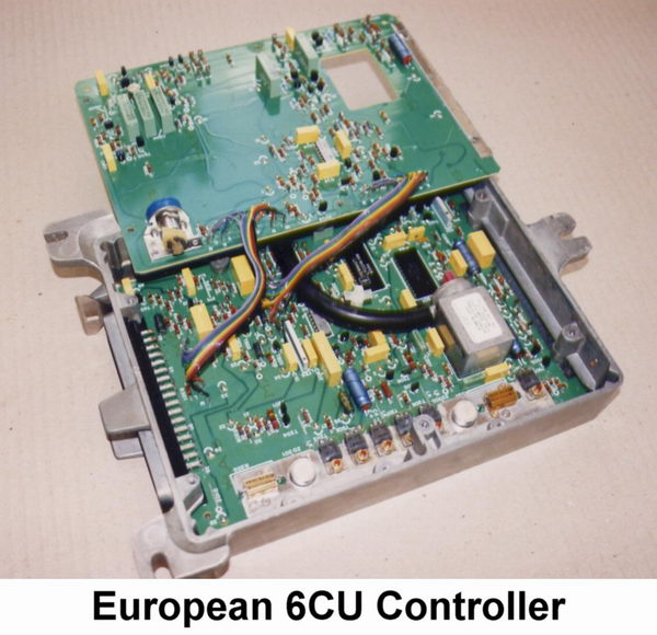
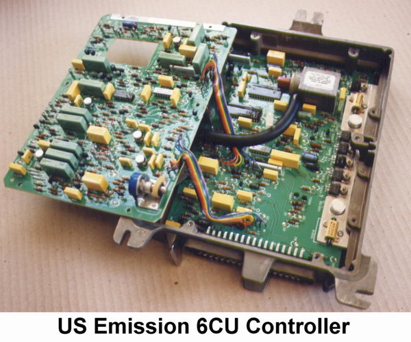
The Lucas 6CU control unit was introduced in 1980 as the key component of the Lucas Digital P EFI system applied to the short lived 10:1 compression V12 engine in the XJS and a small number of XJ12 saloons. It then continued on the HE V12 until 1986 (and in 6 cylinder form as the 8CU for the 3.6 XJ-S from 1983-87).
In designing the system Lucas decided to mount the manifold pressure sensor inside the ECU. The sensor, made by Gulton in California, was widely used in the industry around that time. It comprised a set of aneroid bellows which moved a core within a triple winding to form a linear variable differential transformer (LVDT), a well known type of displacement transducer. It generated a voltage signal varying linearly according to vacuum. The signal was converted to digital form in 128 steps by an Analogue to Digital Converter (ADC) chip and then applied to the main program chip which derived the engine speed value internally from the frequency of ignition sparks. Triggering therefore was from the coil negative terminal; directly in the case of the early 10:1 version; via a resistor inside the ignition amplifier for the HE. The ADC and main chip were custom made by Ferranti and had no commercial equivalents.
The name "Digital P" should not convey the idea that this is a computer based system. This sort of digital technology is at a level known as "simple logic" where counters, registers and other devices operate in a manner that is defined by how they are coupled together. The fueling data, with respect to speed and load, is determined by the state of a block of binary switches which are blown or left intact during manufacture, a bit like a simple ROM memory chip, to create what is known as a "look-up table" but there is nothing that remotely resembles a program or instruction set.
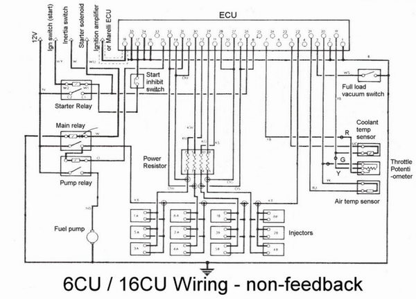
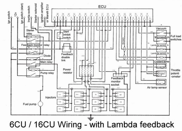
The number derived from the table is passed to a counter driven by a system oscillator (clock). When an injection pulse is initiated clock cycles are counted until they match the number from the "look up table", at which point the injection pulse is terminated. In principle the value stored at each point in the look-up-table would have been set according to data measured from engines on test beds. In practice there would have been a number of designated key measurement sites and in-between values would have been chosen afterwards to give smooth progression. The main chip and consequent fuel mapping is different depending on the ECU having Lambda feedback or not.
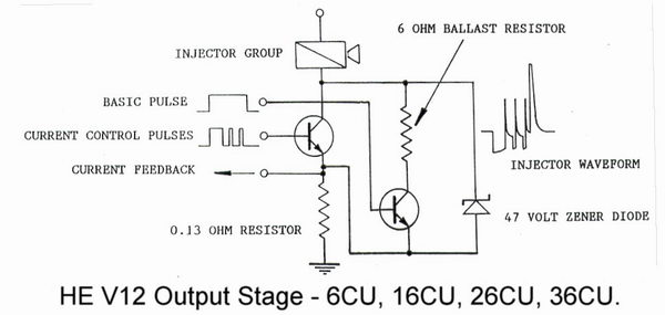
Injectors for each bank were grouped together, the groups firing alternately twice per cycle without being timed to the crankshaft. (8CU on the original AJ6 3.6 used one channel working in just the same way). The pulses from the main chip drove the injector groups through rather complex output circuits designed to turn the injectors on quickly and then control the average current flow. Two output transistors per channel conducted to ground via the same very low value (0.13 ohm) resistor from which a comparator monitored the voltage across the resistor. One output transistor remains on for the entire duration of the injector pulse, the current through it being limited by the power resistor pack. The second transistor switches on and off to control the total current flow. It takes about one millisecond to overcome the inductance of the injectors sufficiently for the voltage across the 0.13 resistor to reach the required level and from then on the comparator controls the switching action of the second transistor. This creates a characteristic waveform with an initial low stage followed by a sequence of spikes from the induced voltages of the switching process, ending with a high spike clipped at 47 volts by a Zener diode protecting the output transistors from over-voltage. This arrangement carried over to the 16CU, 26CU and 36CU controllers which followed.
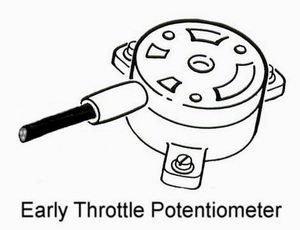
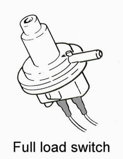
The throttle switch of D Jetronic was replaced by a potentiometer so the position of the throttle was converted to a voltage ranging from 0.32 volts closed, activating the adjustable idle circuit, to about 4.5 volts fully open. Whilst rapid throttle opening triggers a single extra acceleration pulse, rate of change of the voltage signal with throttle opening initiates proportional brief extension of the injector pulses and also weakens during throttle closure. This and other functions such as temperature correction are determined by analogue means according to selected values of resistors and capacitors. These have the effect of changing the ECU clock frequency to make the appropriate corrections. Full load enrichment activated by an external switch was introduced with the HE versions which, apart from the mapping and triggering differences make substitution onto the previous 10:1 engines very inadvisable as they would run with excessively weak mixture at full throttle.
|
|
Pump drive via the relay was also controlled by analogue circuitry in which the presence of trigger pulses maintained a state of charge on a capacitor. While the capacitor was charged high the relay circuit remained active, but the absence of trigger signals allowed it to discharge over about 2 seconds causing the relay circuit to switch off.
Over-run cut off above1500 r.p.m. was activated by a throttle closed signal and a simultaneous vacuum in excess of 21" Hg, but was disabled until fully warm. Once activated the cut off applied until the vacuum fell to about 10" Hg or speed dropped below 1100 r.p.m. Cut off in Lambda sensing versions was active over a much narrower range from 18" back to 15" Hg but in both cases the vacuum effect varied with speed. Quite why this vacuum requirement was thought necessary is a mystery, and it was abandoned for the later 16CU which relied simply on speed and the throttle-closed signal from the potentiometer.
An important addition for some markets was the ability to operate with Lambda feedback and three-way catalysts. Obviously the two cylinder banks are corrected independently and a monitor circuit provides access to check the state of feedback and permit idle mixture adjustment. The signals relate to the feedback state in the following way:-
High monitor V = Low Lambda signal = ECU corrects in rich direction.
An LED setting tool was available but the aim was simply to get both monitors reading as near to 2.5 volts as possible, which can easily be measured with a voltmeter. The monitor output is via a four way plug near to the ECU. The green/white wire reads A bank, the green/pink wire for B bank. The disable link must be removed first (see next paragraph).
To avoid an unstable idling condition the system used the transmission inhibit switch to disable feedback when idling in N or P. The condition is aggravated by the low exhaust temperature at idle allowing the Lambda sensors to fall too close to, or even below, their minimum operating temperature. The disable function could itself be disabled by removal of a link so that idle adjustment could be safely made in N or P. Some people claim that the disable link should be removed when the car is "smog tested" but that is not what it is there for at all and a knowledgeable tester might be inclined to fail the car for having illegal tampering with its emission system. In practice that isn't likely and removing the link will probably help a marginal car to pass but it is still a bodge that shouldn't be necessary for a healthy, properly adjusted car.
Whilst there is virtually no difference in the performance of all 6CUs of similar type when in good condition, we have been puzzled to find that the very similar 8CUs for the 3.6 AJ6 engine can vary quite a lot - so much so that it is hard to find 2 that are quite the same!
The P Digital system was really something of a hybrid - part digital, part analogue - with the usual drawback that a change to one part of the analogue circuitry could influence others.
6CU and 8CU Reliability.
Dry joints (the joint becomes resistive) due to aging seem to be the main problem, aggravated by board flexure due to the weight of the pressure sensor. Hairline cracks can also develop in PCB tracks. The result can be either total loss of one or more functions or just erratic behaviour. Early pressure sensors used to fall apart but that is rare in later units. Main and ADC chips can fail. Burnt tracks are usually the result of excessive voltages being applied to the vehicle, usually from high voltage boost chargers or faulty alternator regulators. The output protection Zener diodes are very robust but can sometimes failure if exposed to excessive voltages.
Blobbing more solder on all the joints can cure dry joint problems in the short term but the only permanent answer is to restore the boards to their new condition. This means the boards must be de-lacquered and de-soldered, all joints re-soldered, followed by an exhaustive full function test and application of a protective coat of lacquer. It is a service we provide.
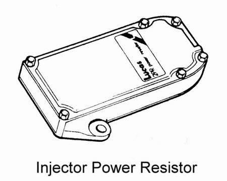
The voltage limiting zener diodes protecting the output stages are robust and mounted in the main heatsink so they are usually able to withstand the heavy peak voltage spikes that occur if the injector power resistor pack becomes faulty or is disconnected. Nevertheless failures can occur which sometimes will result in a direct short circuit holding a bank of injectors on continuously. It is therefore most important that the resistor pack is always connected even though the car may appear to run without it.
A particular problem afflicts 3.6 engined cars equipped with 8CU. We get calls regularly about it and the usual complaint is that the car is running rich and has become erratic on closed throttle. A full explanation about the problem and its solution will be found in the section dealing with the AJ6 engine elsewhere on our website. This problem can only apply to V12 cars if the engine is in a very bad state of repair.
6CU Part Numbers and Applications.
All are preceded by DAC.
1926 - pre-HE Cat
1936 - pre-HE non-Cat
2596, 3062 - HE non-Cat
2597, 3586 - HE Cat
6CU and 8CU Performance Modifications.
6CU is a bit easier to work with than its 3CU predecessor and we can add an external multi-turn dial to permit wide ranging adjustment (up to 25%) to suit large engines. For our Super Enhanced version we change component values and add some circuitry to mimic the program changes which we found worked so well on the later 16CU type, modifying the throttle potentiometer signal to give greatly sharpened response. Also we can delete over-run cutoff for manual transmissions. Although we have in the past added supplementary circuitry to influence the clock frequency and create more extensive non-linear effects for camshaft changes, etc., it is better to move onto the much more flexible 16CU for such applications.
System Problems and Fault Finding.
Despite the apparent complexities the 6CU system is actually not all that difficult to sort out as long as it is approached in a logical manner.
Before thinking about anything else simple causes should be ruled out - i.e. empty fuel tank, water in fuel, crash protection inertia switch.
If the injectors are not firing (they can be heard quite easily with a screwdriver improvising as a stethoscope) then the first thing to do is to listen to the fuel pump. The pump always runs for a couple of seconds at switch-on so this simple action gives a good indication that the system has power. However if the pump does not seem to run then opening the throttles very rapidly should fire a single pulse at the injectors, which would confirm power and raise the possibility of a fault in the pump drive circuit. Grounding the orange wire from the pump relay should make the pump run continuously with ignition on and can be used as a temporary get-you-home fix but not as a permanent repair. If in doubt about the EFI power supply the pink/black wires should always be live with ignition on.
If the pump does run briefly at switch-on the next thing to do is crank the engine which should restart the pump. If this does not happen then the ECU may not be getting a trigger signal which would direct attention to the ignition system.
If all the above checks out then if the injectors are not firing the likely possibilities are faults in the wiring (usually confined to one bank), power resistor, or ECU. Electrical failure of an injector is so rare as to be virtually impossible.
If the engine runs, a good rule of thumb is that pops and bangs in the air intakes suggest weak fueling, bangs in the exhaust system suggest an ignition problem.
If the injectors are firing and weak fueling is suspected then it is always a good idea to check fuel pressure at the fuel rail if only to rule it out as a cause of trouble. It should be 2.5 bar (38 p.s.i.) with no vacuum, dropping to about 2 bar (30 p.s.i.) at idle with vacuum. On a running engine fuel pressure should always be checked under load.
Other possibilities are coolant sensor (if weak from cold), power resistor, ECU. Full throttle weakness would point to an inoperative full load switch or failing fuel pressure.
Excessive richness might be caused by excessive fuel pressure, worn throttle potentiometer or the coolant sensor. If the coolant sensor or its wiring were open circuit the engine would start from cold then swamp out and stall as it begins to warm up. A short circuit to ground in the injector wiring could hold all injectors of one bank on continuously, obviously flooding out the bank concerned. ECUs can also fail causing this.
An open circuit air temperature sensor, or a closed full load switch would cause mild richness that would not prevent the car being driven normally. A suspect throttle potentiometer can be just disconnected when the car should drive almost normally apart from flat throttle response and possibly poor idling (the idle circuit would be inoperative).
A disconnected vacuum pipe would cause richness getting progressively worse as the throttle closes but fueling would be normal at full throttle.
6CU control units can develop faults that might cause weakness, richness, total failure, loss of one bank or loss of fuel pump drive, any of which could be permanent or intermittent. Substitution of a similar type is a useful method of confirming.
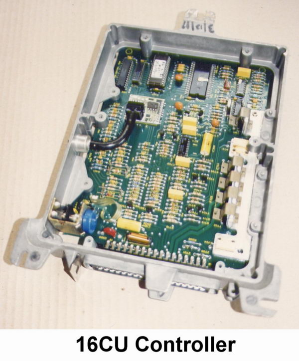
16CU - MICROPROCESSOR CONTROLLER.
This is pin compatible and interchangeable with equivalent HE type 6CUs, at least on cars with Lucas ignition, as all the external components remain the same, however internally the 16CU is completely different, being a true computer system with a microprocessor and programmed memory. All the functions operate according to the data written into the program and there are no analogue functions except for the injector drive output stages which carried over virtually unchanged. The level of technology is an order of magnitude higher than 6CU but the circuitry is actually simpler, whilst at the same time being vastly more flexible. All sorts of embellishments can be written into the program - for example, acceleration enrichment can be set quite independently for 16 different levels of temperature to optimise warm up drivability and emissions. 6CU just had an analogue setting which had to make do for all conditions. That being said very few drivers would ever tell the difference from behind the wheel and blindfold tests actually appear to indicate a slight preference for the "feel" of the 6CU.
The program and fuel data is stored in a 64K PROM memory chip which actually contains 2 sets of data - one for non-catalyst operation and the other for Lambda feedback. A link on the board determines which data is used and extra components must be installed to provide an interface from the Lambda sensors to the microprocessor and also to provide the monitor outputs. Unlike the 6CU the monitor outputs take the form of a square wave with high to low duty cycles representing the amount of correction applied. Fortunately a 47 Mf capacitor across the leads of a voltmeter will convert the signal to a voltage so setting can be just the same as the 6CU, except that the maximum voltage will be slightly lower so mid-range falls around 2 volts.
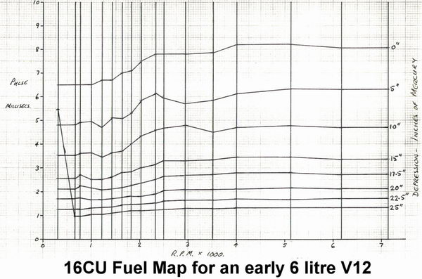
Each fuel map is based on 16 speed points and 8 load points creating a matrix of 128 sites each of which can be set to a different fuel value. Interpolation takes place in 16 steps between adjacent sites to provide smooth progression. There are further blocks of data to deal with all the other parameters such as air and coolant temperature, acceleration enrichment, over-run cutoff thresholds, and so on. The installed data determines every operating parameter and means that the ECU can be set very accurately for any engine specification.
Early 16CUs had much simpler programs and circuitry than later ones but as the mapping was the same they can be interchanged for a similar later car specification.
Triggering signals are taken from the ignition just as in 6CU and also provide the speed information for the program but 16CUs are more susceptible to being upset by ignition faults. When the later Marelli ignition was introduced the trigger function was provide by the Ignition ECU in the form of a square wave pulse so the input sensitivity was altered to suit. This means that ECUs for Marelli equipped cars cannot be interchanged satisfactorily with those having Lucas ignition although they may well start and run.
16CU Reliability.
Whilst durable enough in normal use the output circuitry can be a bit less tolerant of external faults than 6CU. For instance, disconnection (or failure) of the injector power resistor causes the current limiting switching action to occur very rapidly producing repeated sharp induced voltage spikes. Loss of just one of the resistors in the pack is not enough to cause damage - it has to be the absence of both for the affected bank. The resultant spikes can overload the voltage limiting zener diodes causing them to overheat and fail. Failure probably won't occur with the short pulses at idle but it only takes a few seconds at full throttle to burn the diodes out, often scorching the printed circuit board. The diodes can fail open circuit, leaving the output circuitry unprotected from the same overloading, or may go short circuit holding the injectors on continuously. The same problem can arise as a result of a faulty alternator or use of a boost charger but it does require something in excess of 20 volts to cause damage. The earlier 6CUs have more robust Zener diodes which can better tolerate this sort of abuse.
Apart from that and occasional component failures 16CUs are generally very reliable. The increased sensitivity of the 16CU trigger input can cause problems that would not occur with a 6CU when an ignition fault is present. This should be remembered when testing by substitution.
Sometimes people who have had a car running with the lids off the ECU notice that the processor chip gets quite warm. When they find that the chip in another ECU runs cooler (or hotter) the conclusion is easily drawn that something must be wrong. In fact the processor chips are not all sourced from the same manufacturer and different batches from the same source may differ in detail specification although they all work just the same. The operating current can vary depending on the processor and consequently the running temperature of the different types of chip can vary from cool to moderately warm to quite hot. All are normal. Processor faults of any sort are extremely rare.
16CU Part Numbers and Applications.
All are preceded by DAC.
4118, 4585, 6335 - Lucas ignition, Cat
4119, 4478, 4586, 6336 - Lucas ignition, non-Cat
6337 - Marelli ignition, Cat
6338 - Marelli ignition, non-Cat
16CU Performance Modifications.
Almost anything is possible just by changing hex numbers stored in the memory chip. The original PROM can be removed and replaced by a socket. Any program or mapping changes can then be blown into an EPROM memory chip, plugged in and the ECU will simply work according to the new data. It sounds easy but first you need to find out which data controls which function out of many pages of hex coded numbers and neither us nor anybody else is going to tell you how to figure that out.
Whatever the engine or its purpose a chip can be programmed to suit if the right detailed information is available.
When we produced our original Enhanced ECU several years ago we just made minor changes to the main fuel map which made the car feel much more pleasant to drive by eliminating areas set weak to produce best economy test figures. The maximum enrichment at any point was no more than 5% but normal economy hardly suffered because less throttle would be needed for a given rate of progress so part throttle downshifts would be less frequent.
Around the same time we developed several fuel maps for engines using the throttle potentiometer as the main load signal instead of manifold vacuum for multiple intake induction systems and race engines where the vacuum signal would be poor. On a standard engine such a map gives very crisp response to any throttle movement but however much we tried we could not obtain dependable idle quality. We therefore developed circuitry to switch between 2 maps installed in a larger memory chip - one being a standard map for idle, warm up and normal cruise, the second map being the more sensitive throttle sensed one. When the extra circuitry detected quick throttle movement it would switch to the throttle sensing map but if the throttle movement subsequently became more gentle it would return to the standard one. This became our first Super Enhanced ECU.
After a while we found we were constantly searching for 16CUs to convert whilst we had growing stocks of 6CUs which customers with early cars were sending for exchange. Obviously we needed to develop a Super Enhanced version of the 6CU. This we did in the way described earlier, but in the meantime our knowledge of what could be done with the 16CU program was increasing and we developed a single map program which simulated what we achieved with additional circuitry on the 6CU. All of our later Super Enhanced 16CUs use this technique.
We can provide 16CUs with overall adjustment capability - usually only of value for a heavily modified racing applications.
System Problems and Fault Finding.
Much the same as for the 6CU system except that ECU faults are less likely, other than those noted.
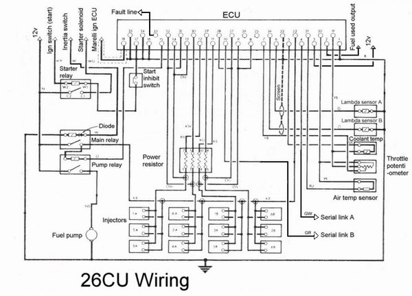
26CU - MICROPROCESSOR CONTROLLER.
This appeared with the facelift XJS in 1991 and is just the next stage of development along the 16CU theme. The circuit and program are both more complex and there is extra protection on many of the input connections. In particular cranking and warm up fueling is much more closely controlled in pursuit of low emissions and provision of acceleration fueling is more complex.
During cranking the injectors fire three times per revolution for an initial period then reducing back to the normal once per rev. This is effective in reducing fire up time in cold conditions by about 60%. After-start enrichment decay rate is linked to number of engine revolutions rather than time as it was in 16CU
Instead of over-run cut off being disabled from a cold start the cut in and out speeds were lifted progressively with decreasing temperatures. For instance below 0 C cut-off only occurred above 3000 r.p.m. and fuel reinstatement was at 2000, while below15 C the speeds were 5000 r.p.m. and 4000. This allowed over-run valves to be deleted.
Full load enrichment, and switching to open loop operation, is activated by the throttle potentiometer, the critical throttle angle increasing with speed so no vacuum or micro-switches are needed for this function. There are no Lambda monitor outputs, the same function being dealt with via a serial data output.
The 26CU program introduced fault logging capability to the V12, the number codes of which are displayed via the trip computer. Sadly there has been a tendency to produce spurious fault warnings and random flagging of codes relating to lambda system malfunctions (FF34,36, 44,45) may have been associated with poor grounding of Lambda sensor heater circuits. Adding extra earth bonding wires between engine and body seem to help this condition.
Although the main wiring remains much the same 26CUs are not interchangeable with 6CU or 16CU types because of minor wiring changes to pins 2,3,4,10, 25, 26 and 33 mainly concerning differences to full load enrichment, diagnostics and feedback monitoring.
It should be noted that the factory repair manual contains many discrepancies in the section devoted to the 26CU system.
System changes.
The inlet manifolds were altered in a number of ways the most obvious being the prominent badges reading "Jaguar V12" set into the top surface in place of the previous ridged arrangement. The fuel rail and injectors were brought up to date using a single mini type fuel pressure regulator (still 2.5 bar - vacuum off) with smaller, faster acting, injectors located by O rings and sockets instead hoses as previously. These differences meant the manifolds could not be easily interchanged with the earlier type although the tracts themselves remained just the same.
In a hot start a 70C fuel temperature switch activates a 45 second timer which limits the provision of raised fuel pressure via a solenoid valve in the regulator vacuum line. A vacuum delay valve allows the pressure to decay gradually during the timer period. This all permitted the fuel cooler to be dispensed with.
Air injection was improved in detail and active for 45 seconds in any start-up, hot or cold.
As noted, over-run valves were not fitted because cut-off remains in operation at all temperatures as noted above.
26CU Performance Modifications.
The EPROM chip containing the program and data is mounted in a socket so it is a simple matter to just swap the chip rather than have to desolder it from the board.
We therefore provide an appropriate revised chip to be installed with any of our conversions and it is not necessary to send the ECU to us.
An ECU self check function requires that the modified chip must always produce the correct checksum number so this must be amended to allow for any mapping data changes or the system will flag up a fault warning.
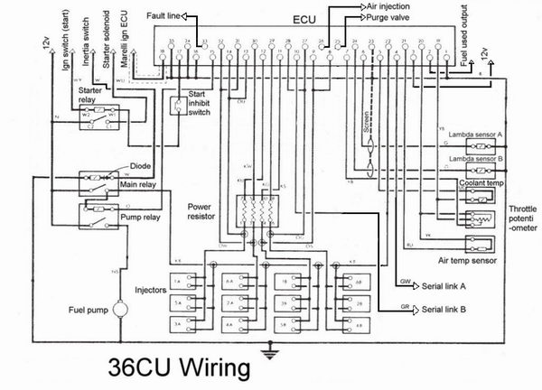
36CU - MICROPROCESSOR CONTROLLER.
This is the final development of the 16CU theme and adds more sophistication to the program, mapping and diagnostics.
The most obvious difference is that there is no idle trim adjustment - the ECU stores lambda feedback values in an adaptive memory to set the fueling automatically.
Adaptive memory is also applied to the throttle potentiometer for the closed throttle signal as long as the voltage falls within the range of 0.22 - 0.75 volts. The recommended setting is 0.6 volts.
Fuel vapour canister purging and air injection, in markets where these are used, are both controlled by the ECU via pins 25 and 26 respectively so it is not possible to interchange with earlier types.
The significance of governing these functions from the ECU is that periodic function checks can be made which also can be used to verify Lambda feedback integrity. Unfortunately this does seem to have introduced an inclination to display a new fault code FF67 relating to the periodic OBD air injection function check, during normal idling, that looks for an appropriate change of feedback correction. If this does not take place within stipulated limits FF67 can be flagged. A tendency to over-sensitivity has been blamed on inconsistent grounding of the heater circuits for the lambda sensors and additional earth straps were introduced as an EPA approved after-fitment cure for these problems. For some markets a revised EPROM chip can also be provided to alleviate the condition.
The tendency for occasional random flagging of codes FF34,36, 44,45 seems to have carried over from 26CU but may be associated with the same poor grounding of the Lambda heaters.
System changes.
Fuel pressure was increased to 3 bar (modulated according to manifold pressure in the normal way) and a twin parallel submerged pump system was introduced allowing for a reduced amount of fuel recirculating through the system, the higher pressure eliminating vapour lock. The pumps are contained in a module so that returning fuel tends to warm the outgoing fuel rather than the entire tank which helps to improve atomisation of fuel issuing from the injectors - of particular value in cold climates.
The primary pump operated in the normal way via a relay switched by the ECU but a separate control module governed the second pump via a second relay according to a speed signal from the Marelli ignition controller. This second pump switched on at 2840 r.p.m. and off when speed falls below 2000 so performed a sort of top-up function in higher demand conditions. Advantages are less current drain, less heat into the fuel system and extended regulator life.
36CU Performance Modifications.
As with 26CU it is a simple matter of changing the EPROM chip for one that incorporates the required changes.