The problem was largely rectified with the introduction of Lucas Digital Injection in 1980 when a much larger balance pipe attached directly to the rear of the plenums was adopted. The rare 10:1 compression engines made for just one year and the subsequent HE versions were therefore much less fussy about the throttle linkage however it is still good practice to ensure that the mechanism is correctly adjusted if these engines are to perform at their best. There is also a possibility that misalignment will cause the voltage signal from the throttle potentiometer to be out of phase with the throttle movement - not usually a problem but our Super Enhanced ECU can then receive inaccurate data about the throttle position which may adversely affect its performance.
The following notes describe a procedure we have found to be effective for setting the linkage correctly.
1A. Early D Jetronic Cars 1976-80. Use a resistance meter to check that the throttle switch, mounted under the throttle quadrant at the rear centre of the engine is adjusted so that contacts 17, 12 go open circuit as the throttle quadrant is moved away from its stop by approx 0.25 mm (0.050"). Adjust the switch position if necessary via the two clamping screws.
1B. Digital EFI Cars 1980 on. Use a digital voltmeter to check that the throttle potentiometer voltage at the closed throttle position reads 0.32 (+ or - 0.02) volts with ignition on and engine not running. This can be measured on the red lead coming from the potentiometer which is located under the throttle quadrant in the rear centre of the engine. Adjustment is via the three clamping screws.
1C. 6 litre Engine 36CU system 1993-96. Throttle potentiometer is a dual device also providing a signal for the transmission. Use a digital voltmeter to check that the throttle potentiometer voltage at the closed throttle position reads 0.6 (+ or - 0.02) volts with ignition on and engine not running. This can be measured on the green/yellow lead. Adjustment is via the two clamping screws.
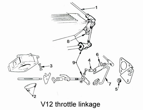
1. Release the two main pushrods (1) taking motion from the throttle quadrant out to the throttle linkages.
2. Ensure that the throttles are accurately centred in their bores and that the clearance is 0.002" (0.05 mm) at top and bottom (2) when closed against the throttle stop screw (3) on the throttle body. Any greater or lesser clearance must be rectified. Wipe any deposits away before measurement and make adjustments at the screw as necessary. Large Bore throttles supplied by us will always be set to the correct clearance and will not require attention. The throttle stop screws should not be altered again from this setting under any circumstances.
3. Check that all spindle bearings (4) in the linkage are in sound condition without excessive side play including the nitrile bushes (5) supporting the rearmost ends of the throttle spindles in the manifold end plates. Renew any with more than minimal side movement - all are available from Jaguar.
4. Check that the bell cranks (6), attached by a link arm (7) to each throttle, just make contact with the fixed stops (8) on the manifold end plate at the closed throttle position with negligible free play to the throttle spindle. If not release the screw clamping the lower arm (9) to the throttle spindle and adjust as necessary.
5. Refit the main pushrods and check that both throttles commence opening together as the centre quadrant rotates 3 - 4 mm from the closed stop. Also check that both throttles reach their respective fully open stops (actually the side of the manifold plenum casting) simultaneously. Adjust the rod lengths if necessary leaving some free play to allow for expansion of the engine as it warms up.
6. Check that the quadrant also reaches the fully open stop at the same time as the throttles. Also ensure that the kick-down switch closes with further movement of the accelerator pedal. Note that XJS accelerator pedals can sag towards the toe board so that kick down and full throttle movement can be lost. This can be rectified by simply pulling the pedal arm as necessary.
7. Start the engine and let it run to fully warm then recheck the movement of the throttles and linkages. Expansion of the engine as it warms up takes up most of the lost motion in the linkages and it may be necessary to re-adjust the main pushrods.