|
|
| Fuel injection and the Jaguar XJ6 4.2 Series 3 | [ Main ] [ 1 ] [ 2 ] [ 3 ] [ 4 ] [ 5 ] [ 6 ] |
|
It may cause some surprise to learn that the first Jaguar to run using L
Jetronic was not an XJ6 but an XJ12 series 2 saloon. In fact this
particular prototype was put together in early 1974 using 2 separate L
systems - one to each cylinder bank. Whilst I cannot now be certain on this
point I rather think it had Lambda sensors and must therefore have been one
of the earliest applications of this technology. Certainly the car was used
over a number of years for emission development work.
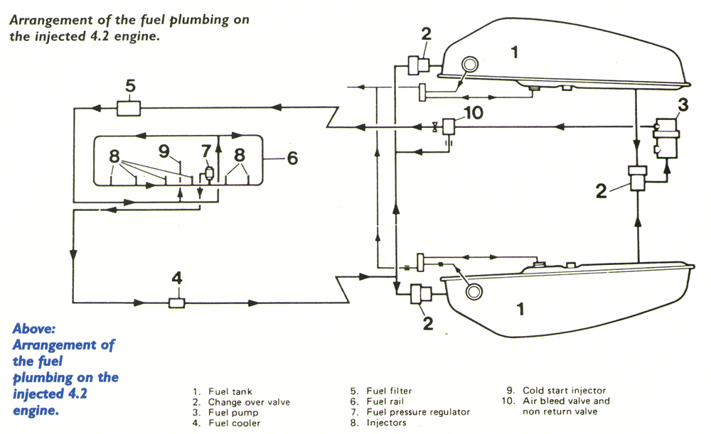
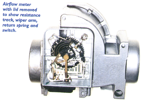
In the UK we tend to identify the EFI 4.2 engine with the Series 3 saloon but it actually appeared a year earlier in Series 2 cars for the US market where the carburetter engines could no longer comply with emission legislation. FUEL PLUMBING & HARDWAREThe general arrangements of the pipe work and various components around the engine are shown in the accompanying diagrams and are well described in various manuals so there is not much point in dwelling on the subject further. In the same way the major components of the induction tract do not need detailed description here. Instead the aim is to deal with topics which are less well understood.THE AIRFLOW METERThe key instrument in L Jetronic is undoubtedly the airflow meter (see photo), composed essentially of a graduated air passage containing a hinged flap which deflects against a spring according to the flow of air through the passage. The flap is mounted on a spindle and directly controls the position of a sliding contact along a resistive track. Although the track itself incorporates a complex array of laser trimmed resistors the principle is very simple: just a potentiometer producing an output voltage according to the deflection of the flap (see diagram). |
Like most things of course the satisfactory operation of the airflow meter
involves some sophistication in its design features. For instance a simple
flap pivoting in the air-stream would be overly-sensitive to any resonant
pulses in the induction tract and any spit-back from the engine would be
likely to blast it back violently against the incoming flow to the limit of
its travel. To resolve these problems a second flap was added at 90 degrees
to the first, pivoting within a damping chamber. The idea was that any
pulse or spit-back striking the two flaps would be largely balanced either
side of the pivot point and any sudden movements would be resisted by the
damping chamber. This worked quite well for pulse absorption but the much
stronger shock wave generated by a spit-back could still blast the flap
onto its closed stop with such severity that the spindle bearings could be
knocked out of alignment causing the flap to jam. Originally a spring
loaded relief valve was built into the flap to relieve such pressure waves
but did not react quickly enough so was superseded by the simple expedient
of a small rubber buffer at the entrance to the air passage.
|
| [ Main ] [ 1 ] [ 2 ] [ 3 ] [ 4 ] [ 5 ] [ 6 ] |
Email aj6engineering@ntlworld.com, Tel/Fax:- 0044 (0)1625 573556 |