|
At this point the Lambda sensing version for use with catalysts added a
further dimension to the control of the final pulse. We saw earlier how the
signal from the Lambda sensor switched between 0.8 volts (rich) down to 0.2
volts (lean) and the duration of the pulse generated by the ECU drifts in
the appropriate direction to correct the error. Note that it is a gradual
correction not an immediate large incremental correction followed by
smaller increments typical of later systems. There is no stable mid-point -
the fueling is always undergoing correction either rich or lean.
Being fundamentally an analogue device the ECU cannot be programmed to
suit the engine as would a more modern one. A laborious sequence of engine
tests has to be undertaken to measure the fuel requirements over a range of
conditions. At each condition a graph called a fuel loop is generated
showing the effect of incremental changes from rich to weak limits. From
this data the airflow meter and ECU are calibrated to obtain the best match
to the specification. This is then refined during road, performance and
emission tests to arrive at a standard which is acceptable with all the
variables resulting from build tolerances, etc. This is not the work of 5
minutes, however, the limitations of the system forces compromises which
modern programmed devices could easily overcome. Despite this L Jetronic
represented a major advance over carburetters.
In the midst of all the calibration work an error nearly occurred due to a
misunderstanding in the interpretation of data. The exact reason is rather
complicated to explain in detail but would have caused a richer than
intended fueling specification. It was spotted just in time by a rather
bright Senior Emissions Engineer called Albert Baxendale who produced a
cleverly worded memo to explain how the discrepancy had arisen.
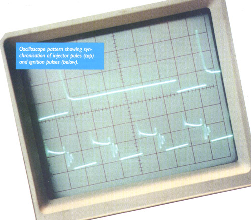
The final pulse is used to drive a pair of hefty output transistors which,
by providing a current path to ground, switch the solenoid injectors on and
off accordingly (see photo). A pack of power resistors each of
approximately 6 ohms is interposed between the individual injectors and the
transistors with the dual purpose of limiting the current through each
injector to about 1.5 amps and isolating any short circuit whilst
protecting the transistors in that event. Note that the two output
transistors operate simultaneously as do all 6 injectors.
|
FAULT DIAGNOSIS - the basics
- Fuel pressure is specified as 2.5 bar (36 p.s.i.) without vacuum applied
but with the engine running this will fall in proportion to the prevailing
manifold vacuum. If in any doubt at all it is always good practice to check
fuel pressure with a gauge, if possible with the engine running and at full
power, at an early stage when trying to diagnose a problem.
- Fuel tank change-over valves are a notorious cause of trouble. The worst
offenders are located behind panels in the back of each rear wheel arch and
when they fail the usual result is fuel becoming transferred from one tank
to the other, possibly overflowing if more than half full, as the return
feed becomes misdirected. Jaguar issued a bulletin in 1979 advising that if
the left hand tank were used before the right hand one after fill up the
problem would be less likely to occur.
- Early cars used a double relay to control power switching into the
system but after some reliability problems separate main and fuel pump
relays were adopted. A failed relay will obviously deprive the relevant
circuit of power and is easily identified.
- Terminal numbers of components are allocated logically so that, for
example, terminal 7 on the airflow meter connects to terminal 7 at the ECU.
- L Jetronic ECUs seldom give trouble and when the system goes wrong the
airflow meter is far more likely to be the culprit. The earlier section
about the airflow meter gives guidance on the matter.
- Do not forget to check the crash protection inertia switch located next
to the left hand front door hinge (A post) if the system has become
immobilised.
- A group of ground leads from the EFI system are fastened at an inlet
manifold bolt towards the back of the engine. These leads seem to be
vulnerable to strain during major repair work and if any become open
circuit this could immobilise the car.
- If the injection system does not seem to be triggering first ensure
that the ignition system is working properly - without sparks there will be
no trigger signal to the EFI system.
- Backfires in the intake usually indicate lack of fuel. Bangs in the
exhaust point to an ignition problem.
- Injectors rarely fail electrically but do sometimes become deposit
fouled with age causing vague symptoms of weak fueling and erratic running.
Ultrasonic cleaning usually cures this.
- If the injector power resistor pack becomes faulty it is unlikely to
afflict more than one injector, however if the connector suffers corrosion
or the terminal contacts become insecure more injectors could be affected.
- Lambda sensors on emission cars do not last for ever but their action
(steady oscillation between 0.2-0.8 volts) can be checked at the back of
the ECU connector with a high impedance voltmeter, but because these cars
have idle enrichment the throttle must be opened slightly to give about
1500 revs. The ground connection to the Lambda screen lead must be intact.
- An open circuit coolant sensor will cause very excessively rich
fueling and whilst the engine will probably start from cold it will swamp
out and die after several minutes running.
- The air intake from the filter housing projects forward alongside the
radiator and has a moulded bell-mouth to smooth air entry. If this becomes
detached, quite easy whilst changing a filter, there will be a noticeable
loss of power. It is no embellishment - it needs to be in place.
- An engine that just seems a bit rich everywhere may have a faulty full
load switch or the vacuum pipe to the switch may be detached (Euro
versions).
- Any air leak downstream of the airflow meter will cause weak fueling
to some extent.
- An engine which just cycles up and down around 1500 revs when the
throttle is opened is likely to be running in over-run cut off. Check the
throttle switch. Because the micro-switch is quite audible it is simple to
adjust so that the "click" occurs as the throttle just begins to open,
however, these switches do sometimes fall apart.
- The cold start injector only fires briefly during cranking to aid
initial fire up. Without it the engine will just take a couple of seconds
longer to start from cold. Don't waste time on it or its thermotime switch
when faced with any other problem.
- Idle mixture on European cars is specified as giving 1-2 % CO but
these elderly engines seem rather happier at 2-3 %.
- A wandering idle speed may be due to the over-run valve leaking as the
spring sags with age. Raising the spring tension by a couple of turns on
its screw will usually effect a cure.
|