|
|
| Fuel injection and the Jaguar XJ6 4.2 Series 3 | [ Main ] [ 1 ] [ 2 ] [ 3 ] [ 4 ] [ 5 ] [ 6 ] |
|
This was a problem which particularly affected Jaguar saloons because the
twin tank system often caused a warning spit-back as a tank ran dry.
Certainly it was quite common for early development XJ6s to have the
induction tract blown off the throttle assembly in such circumstances.
Making the tract more secure only put more stress on the airflow meter but
the buffer largely resolved the problem.
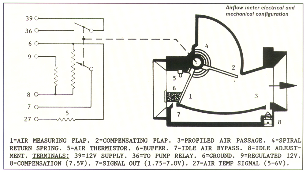
The air passage itself is formed to ensure that the greatest movements of the flap occur at lesser amounts of airflow. This provides better accuracy at times when close control of both exhaust emissions and fuel economy are of most value. A bypass around the flap contains an adjustment screw, sealed in manufacture by a tamperproof plug, to permit the fuel setting at idle to be optimised to suit individual engines. A clever feature that may not be immediately obvious is that the airflow meter automatically provides acceleration enrichment when the throttle is opened quickly. Quite simply the flap overshoots to briefly give a signal appropriate to much higher airflow before settling back to the true position. This is sufficient to ensure quite good throttle response with minimum complication and of course also works in reverse to provide slight temporary weakening when the throttle closes, a common feature of later systems. An air temperature sensor is suspended in the entry to the airflow meter but this only provides correction for air density variations with respect to temperature. Whilst often called mass flow meters these flap type of airflow meters were really volumetric devices and provided no compensation according to barometric changes of density. Such correction is inherent with the manifold pressure sensor technique of D Jetronic and later Lucas systems used on the V12 Jaguar but its absence is a valid criticism of the L Jetronic system particularly in areas with significant altitude differences. In fact there was an early proposal to include a switch for high altitude use but this only arrived on the later US emission cars. The L Jetronic airflow meter was widely used in other systems like Bosch Motronic and Ford EEC IV but in some cases a separate barometric pressure sensor was added to overcome this deficiency. The other drawback is the obvious restriction to airflow into the engine. At the time when L Jetronic was launched this was claimed to be negligible but the writer has actually measured the difference when applied to Rover V8 engines in both naturally aspirated and supercharged forms and in each case found the power deficit to be of the order of 12%. Few people would consider that to be insignificant. We will return to this point later. The remaining feature of the airflow meter is the fuel pump drive switch. This consists of a simple pair of contacts which are held open when the flap is in the static position but which close the moment the flap moves as the engine begins to draw air. The contacts complete the circuit to activate the fuel pump relay therefore the pump will always be disabled when the engine ceases running. |
AIRFLOW METER PROBLEMSThere can be no doubt that many L Jetronic problems involve the airflow meter, not that it is particularly troublesome but it does have several key functions and a fault in any of them is equally inconvenient. One of the most common is for the fuel pump relay switch across terminals 36 & 39 to cease to close properly. The cure is usually just to remove the black plastic cover (which involves some patient work with a sharp knife to gradually break the glue joint) and gently bend the switch contact arms until they close as the flap opens. If the switch is broken then the airflow meter will usually have to be replaced.The wiper arm is secured to the flap spindle by a clamping screw and the wiper itself is adjustable on the arm, being locked in place by a small screw and washer. There is a slender possibility of either clamp screw slipping, perhaps after some sort of shock or backfire. If this should happen it does not take much movement to upset the fueling considerably and if this symptom is observed, and no other fault is apparent, it can be worth experimenting carefully with the slider alignment. The resistance track sometimes wears through, usually around the much used first third of the wiper travel. This will obviously cause erratic fueling and whilst a track from an airflow meter which has failed for other reasons, from a similar car, could be substituted, some trial and error might be needed to set the slider position satisfactorily. Resistance measurements do not provide an accurate means of assessing the serviceability of an airflow meter - it is a potential divider and the system depends on voltages not resistance. There should be smooth transition of voltage on terminal 7 as the flap is moved. Typical airflow meter terminal voltages are:-
The flap spring is fastened to a toothed wheel which cannot really move in service and is best left alone. The spring rate is purposely very low to produce consistent resistance to flap angular movement and relaxation of spring tension is unlikely to occur even after many years. If you must fiddle with the spring be aware that it has a profound affect and always mark the original position of the toothed wheel so that you can put it right again afterwards. At AJ6 Engineering we do relax the setting of the spring quite considerably as a means of reducing the restriction to airflow BUT we also re-calibrate the ECU to match the very different signal this generates, otherwise the fueling would be vastly over-rich. A quite common occurrence is that slight wear in the spindle bearings allows the flap to rub on the housing. This can appear serious but in the majority of cases the flap functions quite normally when the engine is running. Occasionally one finds an airflow meter, or its connector, with a large (100 Mf) capacitor soldered across terminals 6 & 8. This was supposed to be a cure for a drivability problem during warm-up but how effective it was is a matter for conjecture. |
| [ Main ] [ 1 ] [ 2 ] [ 3 ] [ 4 ] [ 5 ] [ 6 ] |
Email aj6engineering@ntlworld.com, Tel/Fax:- 0044 (0)1625 573556 |