|
|
| Fuel injection and the Jaguar XJ6 4.2 Series 3 | [ Main ] [ 1 ] [ 2 ] [ 3 ] [ 4 ] [ 5 ] [ 6 ] |
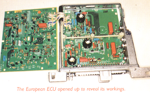
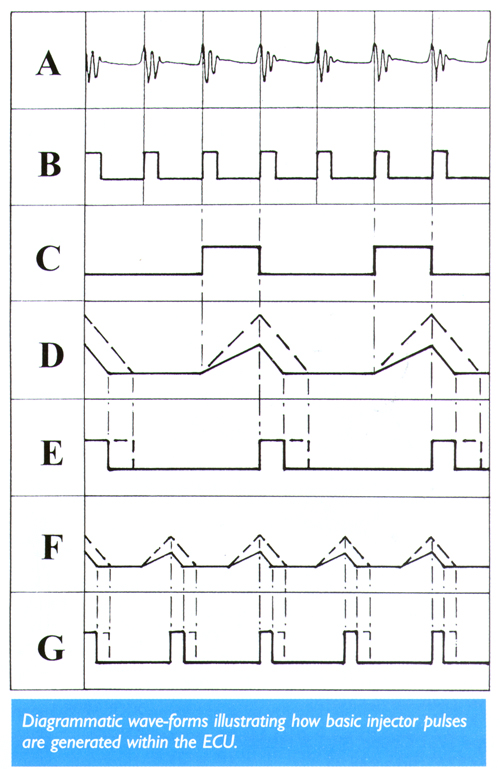
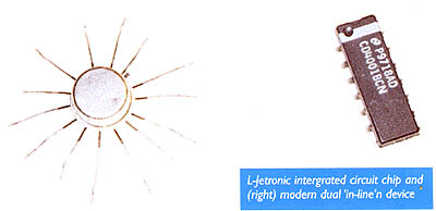
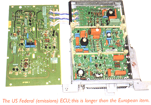
THE ELECTRONIC CONTROL UNITThe L Jetronic ECU (classed as 5CU by Lucas) for European cars is about half the size of that for the old D Jetronic (Lucas 3CU) used on the V12 and was notable for having a much better quality connector with 35 pins. The main input signals (see wiring diagram) are engine speed (at pin 1, derived from ignition pulses), airflow as a voltage input from the airflow meter, and coolant temperature. US emission ECUs are about 3 inches longer to accommodate the extra circuitry needed to deal with the Lambda signals (see photos). The less significant trim factors applied are air temperature correction, full throttle enrichment, idle enrichment (emission cars only) and cranking trim instigated from the starter relay. An idle fuel trim screw is provided at the airflow meter so there is no need for the ECU to be provided with any means of adjustment.ECU OPERATIONThe L Jetronic control unit used analogue technology like its predecessor D Jetronic but at least moved on from having many discrete transistors to using integrated circuit devices composed of many transistors connected to perform specific tasks. The 3 integrated circuits are housed in round metal cases with a clumsy arrangement of 12 or 14 connection wires radiating spider fashion from the underside quite unlike the neat dual in line devices which are now almost universal (see photo). The ECU operating principle was fundamentally based on a counter and several timer circuits responding directly to voltage inputs from the various sensors to generate pulses following simple laws to govern the injector opening periods (see diagram showing wave-forms).
The ignition signal is taken from the coil negative terminal and because voltage spikes as high as 400 volts can be seen at this point the input circuit attenuates the signal to a safe level (A) and creates a trigger pulse (B) from each ignition cycle. This is then applied to a frequency divider which produces one pulse for each engine revolution, at every third ignition spark (C) on an 6 cylinder engine like the XK 4.2. |
The way Bosch describe the generation of the basic injector pulse is
suggestive of an interesting circuit configuration which is widely used
whenever pulses need to be varied in constant proportion with frequency.
Another common application is in the advancing timing light found in almost
every garage workshop, where the set number of degrees remains the same
regardless of engine speed.
A rising edge at the frequency divider output pulse permits a capacitor to charge from a constant current source to create a linear rising voltage ramp (D). The next falling edge from the divider pulse reverses the action and starts the capacitor discharging linearly at a constant current to create a downward voltage ramp. The basic injector pulse is created during the period of the downward ramp (E). Now the clever bit about this is that as the engine speed rises so the time available for the upward ramp becomes shorter so the discharge period takes place from a lower voltage and is itself proportionately shorter (F). If the engine speed is doubled but the airflow remains the same then each cylinder will draw half the amount of air, the charging slope angle will remain the same but will be for half the time therefore the discharge slope will commence from half the height of before, thus the basic injector pulse will be halved (G) and the total amount of fuel injected will remain matched to the total amount of air inhaled. Note that the charging current and therefore the slope of the first ramp is controlled by the airflow meter, a higher flow condition being shown dotted, whilst the discharge current and the downward slope of the second ramp are always constant. By this relatively simple circuit configuration the basic injector pulse is inherently corrected according to any changes of speed and airflow. Actually it is quite impossible to verify that all this really happens. The basic pulse is real enough and it does vary as described but the business with ramps up and down can't be seen by poking around the ECU with an oscilloscope, so perhaps we have to regard it all as a notional explanation rather than an exact one, although it certainly is consistent with how the ECU behaves. To compound the mystery an explanatory document issued within Jaguar Experimental Department in 1978 to introduce L Jetronic stated, and I quote verbatim, "the fueling information is carried in a memory so that for any combination of intake airflow and engine speed the memory gives out a signal which is proportional to the amount of fuel required". In fact, L Jetronic does not use memory technology at all but maybe this illustrates how unfamiliar engineers were with electronic systems at that time and so such an explanation was thought to be adequate. Just because something is in print doesn't mean it is necessarily accurate! Having generated the basic injector pulse it is then passed through a multiplier stage and the various corrections for coolant and air temperature, battery voltage, full load enrichment, cranking and after-start enrichment are applied. Of course, unlike modern digital systems which scan the various inputs and convert their signals into hex code for manipulation according to a program, in early systems like L Jetronic the voltage signals from the various sensors directly influence timer circuits to produce the final injector pulses. We have just seen how this happens with the airflow meter signal in the creation of the basic pulse and the others have a similar effect during the multiplier stage. |
|
|
| [ Main ] [ 1 ] [ 2 ] [ 3 ] [ 4 ] [ 5 ] [ 6 ] |
Email aj6engineering@ntlworld.com, Tel/Fax:- 0044 (0)1625 573556 |