| Menu |
| Homepage |
| NEW & REVISED BOOK! |
| Personal intro |
| Philosophy |
| Intro technics |
| FAQ |
| Exhaust systems |
| Exhaust overview |
| E-type |
| XJ Saloon S1,2,3 |
| XJ40 (AJ6&V12)/X300 |
| XJS |
| XK8/XJ8 |
| TT exhaust explained |
| The Jaguar V12 |
| V12 Performance |
| Stretching the V12 |
| E-type EFI conversion |
| Lucas EFI |
| Vacuum advance |
| Ignition systems |
| V12 throttle linkage |
| Article: V12 Engine |
| V12 Archives |
| The Jaguar AJ6 |
| AJ6 Performance |
| 3.6 Richness |
| AJ6 fault codes |
| AJ6 Archives |
| The Jaguar XK |
| XK Performance |
| Article: XK Engine |
| Article: 4.2 EFI |
| The Jaguar V8 |
| V8 Performance |
| AJ6 Superchargers |
| Superchargers |
| Supercharging article |
| Suspension & Brakes |
| ECU repairs |
| Miscellaneous bits |
| Glossary |
| Prices & ordering |
aj6engineering@ntlworld.com
Updated August 2016
Visitors:
82495090
|
|
Introduction.
I produced the original article on this subject in 1988 for the then forthcoming Jaguar Quarterly magazine, known these days as Jaguar World, in which it was published during 1989. Although many people will regard the Bosch D Jetronic system as out-of-date and irrelevant I do not agree with that view at all. It is the ancestor of all modern EFI and engine management systems and I think if more people had a thorough understanding of this relatively simple system there would be a far better general grasp of the workings of later systems. There is no better starting point for anyone who wants to learn about this important subject.
It seems a good opportunity now, some 15 years or so later, to make a few revisions and additions to improve on the original text, and put right the inevitable errors which crept in at the time (hopefully without introducing any more).
I have added some brief comments at the end about modifying the D Jetronic system for high performance applications.
Roger Bywater.
The Background.
It was never intended that the Jaguar V12 power unit should be fueled other than by electronic injection and it is only of historical significance to mention that the promising AE Brico system around which much early work revolved was killed off at a late stage. Jaguar had little option, in view of the substantial investment to which they were committed, other than to hurriedly introduce the V12 with the less thoroughly developed quadruple carburettor arrangement, which performed tolerably well, except from a cold start, when fuel consumption and exhaust emissions were horrendous.
During the late sixties Bosch had introduced their D Jetronic electronic injection system of very similar type to the Brico, both owing much to the earlier pioneering Bendix designs. Bosch announced a more advanced system, L Jetronic, in 1972 and the writer remembers a V12 Jaguar saloon equipped with a dual version, one per bank, in 1974 or thereabouts, anticipating BMW's similar dual Motronic arrangement of their more recent V12 by many years. L Jetronic became very widely used in various forms but Jaguar were probably wise to adapt, via Lucas, the by-then ageing Bosch D Jetronic, partly because of its similarity with the Brico system, but also because it was known to be reliable.
Operating Principles.
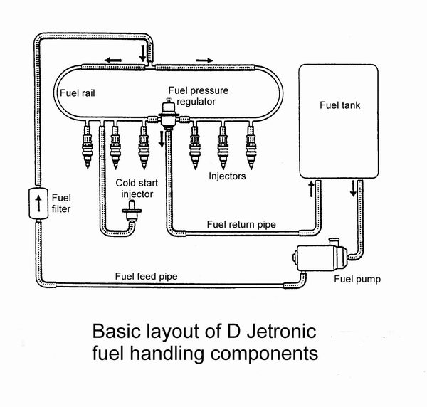
The basic D Jetronic system employs a recirculating fuel system in which a constant supply of fuel is pumped from the tank and delivered through a fine filter to the injectors at constant gauge pressure (usually around 2 Bar / 30 p.s.i.). A spring loaded regulator valve (2 on the V12) spills off the excess fuel which returns to the fuel tank. The flow though the system is always more than the maximum demand ever required by the engine.
AJ6 Engineering.
January 2004.
The injectors are simply precision solenoid operated valves which are opened for a brief period once per engine cycle, when they introduce a fine conical spray of fuel into the inlet ports, just upstream of the inlet valves. The amount of fuel injected is determined solely by the injector opening time (injector pulse width) under the control of an Electronic Control Unit (ECU). In most D Jetronic applications the injectors were divided into two alternate firing groups but there were instances of 8 cylinder applications where 4 groups were used. Each injector group is fired once per cycle, timed so that one injector fires during the induction stroke whilst the other(s) must fire progressively earlier in the cycle of their respective cylinders. Obviously some cylinders would be better timed than others but to the disappointment of many purists it didn't really seem to matter very much. That being so, if the firing points of the two groups were reversed there was a definite loss of drive quality. In this respect it is true that 'a little bit of richness can cover a multitude of sins' and really the D Jetronic firing arrangement would certainly not be good enough for modern engines operating with stoichiometric mixtures, but it was much better than carburettors.
Note that because the fuel rail pressure is constant the pressure drop across the injectors varies with manifold pressure and the fuel delivery therefore varies slightly in unison. This was not arranged deliberately but was simply of little consequence in a system like this where, as we shall see, the ECU was fine tuned, or calibrated, to best suit the engine requirement rather than the now universal approach of using programmed data directly related to fuel quantity.
The injector pulse time is governed by engine speed, engine load, coolant temperature, air temperature, and throttle position according to the inputs from appropriate sensors attached to the engine. The quantity of fuel supplied to the engine is determined by the time for which the injectors are open, known as the pulse duration. This will generally vary between 2.5 and 10 milliseconds (ms = thousandths of a second) from closed throttle to full load, but the closing and opening actions of the injector(s), during which the flow rate sweeps between nothing to full flow, take around 1 millisecond each so the true flow at short pulse durations is lessened accordingly. Having said that the relatively small difference between the flow at idle (around 3 ms) and at full throttle (10.5 ms) demonstrates quite vividly the magnitude of the internal losses of an engine when throttled.
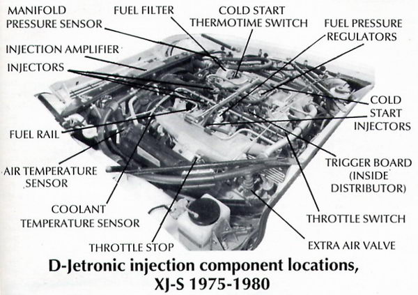
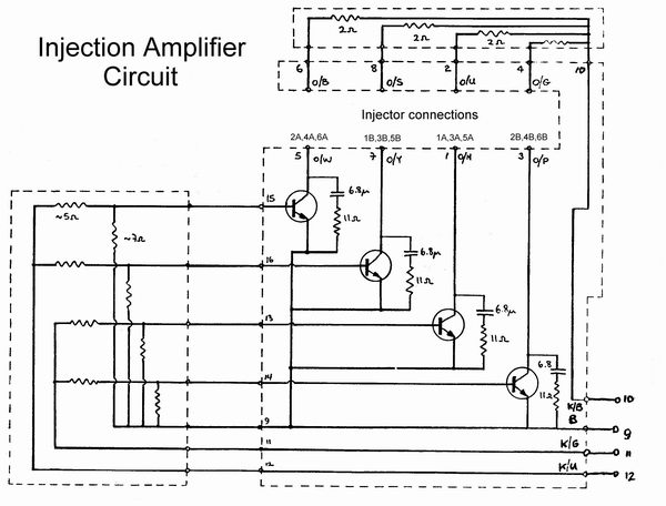
When being developed via Lucas for the Jaguar V12, the inability of the original D Jetronic ECU to drive twelve injectors was easily overcome by adding an amplifier, mounted over the radiator, conveniently dividing the injectors into four groups of three. These are so arranged that injectors to odd cylinders of one bank fire in unison with those of even cylinders of the other bank. This worked well enough for the early flat head V12 but was inadequate for the more fussy HE V12.
The Method of Operation.
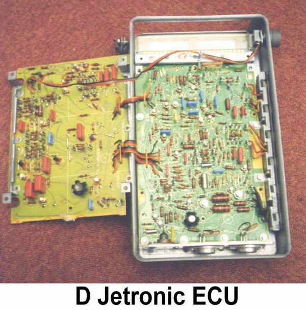
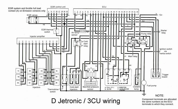
By modern standards the D Jetronic (or Lucas 3CU) control unit is rather primitive being composed of around 40 or so discrete transistors and a load of resistors, capacitors and diodes. Not a single integrated circuit, the basis of all modern electronic systems, is to be found in it. It is a system of additive pulse generators, influenced by currents and voltages derived from the various sensors around the engine.
Of primary importance are the manifold pressure sensor, which provides a measure of the engine operating load, and the coolant temperature sensor, which enables the ECU to provide the considerable extra enrichment required by a cold engine and then to weaken off as the engine warms up.
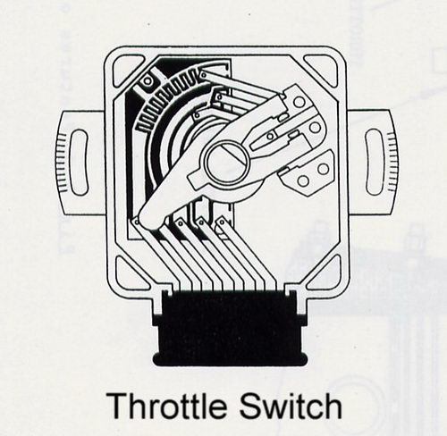
Secondary inputs are from the air temperature sensor, enabling the ECU to trim the fuel input accordingly, and the throttle switch. This identifies a closed throttle condition, provides acceleration enrichment when the throttle is opened briskly and, in US emission versions only, signals a wide open throttle condition.
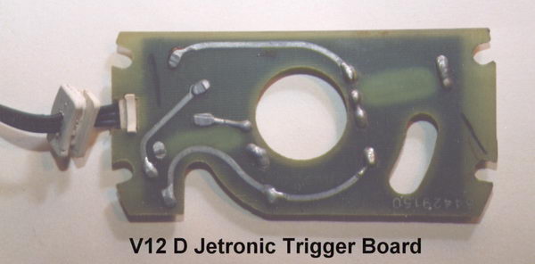
Injector pulses are timed and initiated by trigger switches mounted diametrically opposite to each other within the distributor. Bosch had used a pair of miniature contact breakers (duplicated for the rare 8 cylinder / 4 injector group system mentioned earlier to provide the necessary 4 trigger pulses) in earlier applications but this was not easy to arrange within the Jaguar V12 distributor, quite apart from being seen as a retrograde step on an engine with electronically triggered ignition. By simply mounting a magnet in the "balance mass" of the rotor arm it was possible to operate magnetic reed switches encapsulated in a "trigger board" without any great difficulty although greater reliability was obtained subsequently by adopting "Hall Effect" sensors (magnetically switched transistors) instead. The early reed switch board had just three wires in a ribbon (one channel each side and ground in the centre) while the Hall Effect type had a fourth wire for connection to the switched ignition 12 volt supply.
As each trigger briefly closes a circuit to ground it initiates an injection cycle for the associated injector group starting with the primary pulse. The frequency of triggering provides a measurement of engine speed which influences the pulse circuits to provide the appropriate correction factor to the primary pulse. This function, known as the speed law, causes the injector pulse to increase gently until the speed of maximum torque is reached after which the pulse starts to shorten. This can be represented by a graph plotting pulse width against speed on which a line curves gradually upwards to a hump before finally tailing off. Component selection determines the upward and downward slopes and therefore also the peak of the curve. In this way the fuel input is matched to the volumetric efficiency of the engine although obviously without the precision (not always fully exploited) which modern programmed systems are capable of.
The manifold pressure sensor, mounted above and behind the radiator on saloons, and just behind the radiator on the RH inner wing on XJS models, is really a sealed transformer with an inductive core attached to a pair of anaerobic bellows. The bellows cause the core to move according to vacuum and the resulting change of inductance in the transformer windings alters the injector pulse in unison. Clearly the bellows must be evacuated to provide consistent results and eliminate any errors resulting from changes of temperature.

On European non-emission cars the sensor incorporates a diaphragm which increases core shift as full load is approached thereby providing 10% power enrichment. US emission cars have a slightly different pressure sensor with one half of the bellows open to atmosphere to provide barometric and altitude correction, full load enrichment then being applied instead at the throttle switch via pin 14, which is unused in European versions.
The coolant temperature sensor, located behind B bank thermostat, provides extra enrichment when the engine is not fully warm. During cold start and initial warm up this enrichment is considerable and whilst, again, it was accomplished within the limitations of component selection, the improvement over carburettors in the ability to control this phase was vital for Jaguar to continue selling, in emissions conscious USA and California particularly, during the 1970s.
Air temperature is measured via the sensor in the left hand air duct, but is only a trim factor applied to the overall fueling.
Both temperature sensors are thermistors, the resistances of which fall with rising temperature. The nominal resistance of the coolant sensor is 330 ohms at 80 degrees C and that of the air sensor is 300 ohms at 20 C.
Located under the throttle pedestal towards the rear of the engine is the throttle switch. This activates special conditions, namely, idle, over-run cut off, and acceleration enrichment (also full load enrichment in the US emission version as mentioned before), simply by completing a chassis/ground return circuit for whichever function is required. Acceleration enrichment is provided via sequential contact points producing extra short pulses at the injectors whenever the throttles are opened sufficiently rapidly, the feature being disabled during slow or reverse movement by deliberate lash in a spring contact built into the throttle switch arm. Acceleration pulses only pass to whichever group of six injectors fired most recently if the throttle is opened when the engine is not running. The normal injector pulses are also extended slightly when acceleration pulses are activated, then decay back to normal over about one second or so.
As an historical note some early applications of D Jetronic used a pressure switch to activate full load enrichment - a technique which returned to favour on many later systems (for example, XJ6 L Jetronic and Lucas 6CU HE V12).
Over-run cut off was not applied to early cars with automatic transmission or any examples with manual transmission. In the latter case it was omitted to avoid an unpleasant shunting condition with oscillation between the cut-in and cut-out speeds on a trailing throttle. These cars were therefore equipped with over-run valves which will be described subsequently.
The low end fueling of ECUs for manual transmission cars was different. An auto transmission cannot allow the engine to run at full throttle below the stall speed of the torque converter (about 1800 r.p.m.) but with a manual transmission the engine could, and probably will, have to run down to much lower speeds. The "match" of the fueling laws is therefore biased accordingly.
Adjustment is provided on the ECU to enable the idle fueling to be optimised to give the required 1 - 2% exhaust CO emission. This adjustment has no effect apart from when idling with the closed throttle signal activating the idle fuel circuit.
Generation of the Injector Pulse.
The method by which all the above sensors influence the final injector pulse is essentially as follows:-
The trigger signal activates a constant current circuit which charges a capacitor linearly to create a rising voltage ramp and the coupling of the pressure sensor in combination with speed determines the time interval for which this ramp can rise before the capacitor is discharged to ground. The other side of the capacitor is instantly pulled negative by an amount equal to the final ramp voltage and then proceeds to charge linearly back to its baseline voltage, creating a second ramp but this time of variable slope. This slope angle is set by the coolant temperature sensor, throttle movement (acceleration enrichment pulses), and idle trim to provide the appropriate corrections. After-start enrichment also changes the angle of the second slope which then recovers steadily to its normal condition over about half a minute, the acceleration pulse extension having a similar effect but decaying away in not much more than a second or so. The full load signal from the throttle switch, used on emission versions, extends the rise time of the first slope.
To provide over-run cut off the first slope is made inactive thereby halting the entire pulse generating process, although a very brief pulse (about 0.01 ms) does still appear at the injector outputs as a consequence of the trigger action. Fully warm, over-run cut off will only take place at closed throttle when engine speed rises above 1450 revs and fuel reinstates as it falls to 1100 revs. These speed thresholds are lifted with lower temperature operation.
The two ramp periods add together to determine the duration of the final output pulse sent to activate the injectors. For an output pulse of 10 milliseconds, when fully warm, the first ramp lasts approximately 4 milliseconds and the second ramp lasts the remaining 6 milliseconds.
Note that the system does not allow pulses from two injector groups to overlap so the injector size must be selected to deliver all the fuel in one revolution. Quite how the rare 4 group system dealt with this is not known to the writer but presumably either some overlap was possible or the injectors were large enough to deliver all the fuel in half a revolution.
The general principle of using one ramp to set another with the slope of each ramp determined according to various control factors is a well known technique in non-digital electronics. It was shown earlier how the speed parameter followed a graphical pattern known as the 'speed law'. The affect of the other sensor inputs can be represented in a similar way so any given ECU specification would follow a series of graphs or laws.
Programming is not a word which would apply here but the ECU development process would be something along the following lines:-
Steady state dynamometer tests with an adjustable ECU would first be used to plot the engine fuel requirement (pulse width) over a range of speed and load conditions. An ECU would then be 'tuned' by component selection to 'best match' the requirement. Cold start, warm up, acceleration and other factors would initially be set on the basis of past experience. These settings would then be refined during further dynamometer work, emission tests and road testing over a long period. This would involve a number of similar cars and ECUs to determine an acceptable tolerance spread. ECUs can then be manufactured and calibrated by component selection to match the required standard.
Fuel Plumbing.
D Jetronic introduced the recirculating fuel system used on just about every electronic system since until the recent advent of non-recirculating systems. The pump draws fuel from the tank and delivers it to the fuel rail(s) (the pipe which feeds the injectors) having an exit to a pressure regulator which maintains constant pressure at the injectors and spills excess fuel into a return pipe to the fuel tank. The flow rate in the system is always in excess of the maximum that could ever be required by the engine. D Jetronic regulators are adjustable but should be set to the correct pressure.
The V12 installation uses separate fuel rails and regulators for each cylinder bank but the two are linked and it is important for both of the regulators to be correctly adjusted so that the slightest backing-off on either will immediately cause a pressure reduction. Twin tanks in XJ12 saloons have a system of solenoid valves controlled via the tank selector switch to direct recirculating fuel to the tank from which it originated. Any air entering the system when a tank runs out is purged by a bleed valve located in the spare wheel well.
There is a non-return valve built into the pump, and another attached to the air bleed unit on saloons, which are intended to retain pressure in the rails after switching off with the intention of preventing vapour lock during a hot restart. Unfortunately this can still happen, partly because of the relatively low fuel pressure, and was a minor irritation associated with the D Jetronic system.
Because of the fine working clearances of the injector internals it is essential that no foreign particles can enter the fuel rails and a high quality filter is provided in the feed pipe as it joins the fuel rail. The filter capacity is not very great and it is important that it is changed at the recommended intervals.
The ECU controls the pump via the pump relay and activates it for about 1 second at switch-on to pressurise the system. The trigger signals then reactivate the pump to keep it running continuously whilst the engine is turning over or running. If the engine stalls the pump will be switched off after 1 second or so for safety reasons.
Cold Start Injectors.
Cold start injectors, producing a fine fuel mist, are situated one in each plenum facing the throttle and they only ever operate while the engine is being cranked by the starter at low temperatures. They are therefore far less important than some people think.
Some very early applications of D Jetronic had the cold start injector controlled from the ECU but by the time the system was being developed for the Jaguar V12 this arrangement had been superseded by having separate control via an electrically heated bimetal device called a thermotime switch powered from the starter relay. The self heating action limited operation to a maximum of 8 - 12 seconds although the on-time would be progressively less the higher the prevailing coolant temperature at start up. On the V12 the thermotime switch was situated just behind A bank thermostat and because there were two cold start injectors a relay was introduced to switch the extra current.
The effect of the system was to reduce cranking time to fire-up and it is doubtful if the added complication is worthwhile except for very cold start conditions. The cold start system was deleted from the later HE V12 in around 1982 partly because it had better mixture quality as a result of using two squirts per cycle instead of one.
The Induction System.
The need for a steady manifold pressure signal as a measurement of engine load requires a plenum chamber type of inlet manifold (obviously two on the V12) with individual tracts leading to each inlet port. Air enters the plenum through a single throttle. This is in fact an indirect method of determining the fuel requirement because it relies on the engine being a pump of fixed volume per cycle and the induced quantity of air is deduced from the pressure of the air in the system as measured at the plenum.
If the pumping efficiency of the engine should change due to wear or some sort of fault the load measurement will become erroneous so the method has less accuracy than the direct air flow method but has the advantage of being less restrictive at full throttle.
It was noted than early versions and manual transmission cars did not have over-run cut off. Because fuel mixtures at very low manifold pressures become incombustible and can cause violent exhaust back firing over-run valves were fitted to these cars at the front of the inlet manifolds to limit the vacuum that could be produced in the over-run condition.
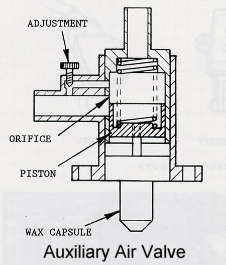
When the engine is idling the main air flow enters through an auxiliary air valve which has an adjustment screw to set the hot idle speed. The valve is attached to the coolant rail at the rear of B bank cylinder head and incorporates a waxstat bulb which moves a slide valve over an orifice. This provides extra air for cold operation and gradually closes off as the engine warms up.
The air filters have shield plates across the throttle area to prevent destruction from spit-back when a tank (saloon) runs dry. The superficially similar XJ6 filters are not an acceptable substitute and the edge seal is quite different, The spit-back phenomenon could easily dislodge early filter boxes causing a sudden increase of induction roar so later filter boxes have four deep engagement lugs instead of the shallow flange used originally.
Exhaust Gas Recirculation (EGR).
On US emission V12s EGR was administered via solenoid valves mounted under the throttles which were opened and closed by a small EGR electronic control unit. This acted according to several input signals, one from an injector drive output from the ECU providing a speed signal, two from the throttle switch indicating closed and full throttle conditions, and one from a thermal switch which holds the system off until near to fully warm. The fueling did not change when EGR became activated other than in consequence of the effect of EGR on the prevailing manifold pressure to maintain load.
EGR was not applied at engine speeds above 3500 revs in any circumstances, nor at closed throttle, nor at full throttle, and not from cold. Put another way it is only applied during part load operation below 3500 revs. Obviously disabling or removing the EGR system will not make any difference to full throttle performance although it might make a slight improvement to part throttle response and economy.
There was an unexpected noise problem when this EGR system was first used because it allowed exhaust sound to emanate from the air intakes. The writer recalls experimenting with little silencer boxes where the EGR pipes came out of the down-pipes but repositioning the take off points to the front of the Y joint/catalyst cone proved to be a more eloquent solution.
It is easy to mock the approach of matching D Jetronic's fuel laws to the engine on a "best fit" basis but it was a considerable improvement over carburettors of the time. In reality a good many of the sophisticated aftermarket programmable ECUs are never setup much closer than D Jetronic simply because it is not usually practical to spend the time necessary to refine the mapping to the accuracy that is theoretically possible.
PROBLEMS.
1. Fuel Handling. Pump noise is not unusual and may only be due to an excessively firm mounting. Fuel pressure should be 30 p.s.i. or 2 bar (some applications other than Jaguar may differ slightly) and can be measured simply by disconnecting one of the cold start-injectors and attaching a suitable accurate gauge to the stub on the fuel rail. Although steady decay over 30 minutes or so after switch off is permissible, rapid pressure loss should be investigated and will result in hot start problems through vaporisation. In hot weather D Jetronic can suffer a degree of vapour lock in any case which is one reason why later systems generally run at 2.5 to 3 bar pressure, which of course would cause over-enrichment on D Jetronic. In hot climates it may well be a good idea to run D Jetronic at 2.5 bar pressure and have us trim the ECU weaker to compensate.
Likely causes are leaks through regulators, injectors or, particularly, pump non-return valves, identifiable by clamping the various pipes in turn and noting the effect on the rate of pressure drop. A worn pump or partly blocked filter or pickup strainer may allow correct pressure to be obtained at idle, but could be unable to sustain it under high speed/load. Hoses do deteriorate and should be checked periodically for security and any replacements MUST be of the correct fuel resistant specification. The system can be depressurised by removing the orange wire from the pump relay while the engine is kept running with acceleration pulses but some residual pressure will usually remain. ALWAYS blow out between the cylinder heads after any fuel spillage. Failure to do so can allow vapour to collect in and around the distributor cap, which can then explode on start up - YOU HAVE BEEN WARNED.
2. On saloons the solenoid operated change-over valves, which ensure fuel is drawn from, and returned to, the selected tank, can fail, leaving one tank unselectable or rapidly draining one tank into the other. If the tanks are more than half full in total, after filling one tank the remainder will be ejected through the vent system. Fortunately the valves are easy to change, later cars having a separate return valve to each tank in the rear wheel arches, earlier cars having a single three way valve in the boot well, along with the three way selection valve.
3. Injectors. Healthy injectors produce a clearly audible sharp clicking sound but a stethoscope should be used to check them individually. It can be helpful to remove the connectors one at a time to assess the effect on the engine as it idles. The green body injectors fitted to D Jetronic V12s have a design of pintle valve which can be relatively easily clogged by fine debris. Water contamination of the fuel must be cleared immediately or emulsions formed around the pintle will cause jamming, sometimes within hours. If ignored all 12 injectors are likely to fail during ensuing weeks and at around �60.00 each this becomes expensive. If an injector fails open whilst running it will often result in an alarming cloud of "steam" which is actually fuel vapour - a rather dangerous condition. If the engine is then switched off the spark plug of the offending cylinder, or all plugs of that cylinder bank if unsure, should be removed and the engine turned over carefully, to prevent a hydraulic lock when next attempting to start, which can easily damage the starter or ring gear. Do not fit injectors of a different type as the flow calibration will not be compatible. Electrical failure of injectors is extremely rare, but for those who wish to check, the resistance of the injector winding should be nominally 2.5 ohms.
4. Injector Amplifier. If a problem is found to be common to three injectors grouped as described earlier then the amplifier may be faulty. It is not likely that more than one of the four output channels will have failed. As adjacent injectors are never in the same group it is simple to switch connectors around to aid diagnosis.
5. Trigger Board. Failure of this component is probably the most common cause of breakdown. If a trigger switch fails "open" the whole system will cease to function but a "closed" switch failure will leave 6 cylinders active. Trigger operation can be quickly checked with an AJ6 Ignition/Injection Tester or less positively with a resistance meter while cranking the engine, although, annoyingly, failure can be intermittent.
6. Temperature Sensors. These are generally very reliable and if the coolant sensor should become open circuit, by a detached connector perhaps, the fueling would go vastly rich allowing cold starting but then swampinq the engine after a minute or two. An open circuit air thermistor is far less disastrous causing about 10% overall enrichment which many people might not even notice. The following sensor resistance values are typical but minor variations will be found:-
| Deg C | Ohms - Coolant temp | Ohms - Air temp |
| 0 | 5.9k | 650 |
| 25 | 2.0k | 250 |
| 60 | 600 | 80 |
| 80 | 330 |
Coolant sensors have been known to go open circuit briefly, thereby stopping the engine, then recovering too quickly for the fault to be detected. If this is suspected then the sensor should be renewed.
7. Pressure Sensor. Any break in continuity through the pairs of windings (terminals 7,15 & 8,10) or the wiring to the ECU will immobilise the system. The full load sensing diaphragm (European versions) is prone to fracture allowing leakage of vacuum which if only very slight is tolerable but otherwise will enrich part throttle fueling. Any leaks in the connecting pipes will have similar effect.
8. Throttle Switch. These are unjustly blamed for many problems but if disconnected the car should still drive reasonably well although the idle may be erratic. Being a mechanical device the switch can be opened up for inspection therefore worn tracks or faulty contacts can be easily spotted although the lost motion arrangement for the slider is intentional (to avoid acceleration enrichment on throttle closure) and should not be regarded as a fault. The idle switch, via terminals 12 & 17, should open as the central throttle quadrant is moved about 1.5 mm away from the idle stop. Slacken the clamp screws and adjust if required.
9. Throttle Linkage. A high proportion of V12 problems are due to the throttle linkage being incorrectly adjusted. Difficulty arises because the balance pipe between banks is too small and because the pressure sensor is Tee connected to a further pipe running across between the plenums. Any imbalance in the vacuum drawn by the two banks is averaged causing one bank to be weak and the other rich. It is therefore vital that the throttle linkages are set so that both throttles begin to open simultaneously, and move exactly in unison to reach full throttle together. This, probably more than any other factor, is the key to setting up a D Jetronic V12 to give of its best, yet few people are aware of it and many cars will be found to have been wrong to a greater or lesser extent throughout their lives. Because of the effects of expansion the linkage should be checked with the engine fully warm. The throttle discs should first be centralised on the spindles and the stop screws set to give 0.002 inch clearance all round. If allowed to contact the body a disc can seize within it due to contraction when the engine cools. The central quadrant should rest against the respective stops at either extreme of rotation and the final pedal movement should operate the kick-down switch on automatics. On XJS models the pedal often sags and loses travel, easily rectified by gently bending it away from the toeboard. Throttle springs can lose tension with age and should be renewed if they do not close the throttles properly when idling.
All idle speed adjustment should be carried out only at the large screw on the auxiliary air valve situated behind B bank air filter to give 750 - 800 r.p.m. when hot. The cold idle speed should be around 1000 r.p.m. and if unacceptably high or low the air valve may need replacing but air leaks should be checked for first. A lazy air valve that does not close off far enough can sometimes be improved by pushing the top casting slightly further in with the aid of a vice (using a tube to protect the wax bulb).
10. Over-run valves, mounted at the front of the intake manifolds, tend to lose spring tension with age, causing high or unstable idle speed but fortunately they can be easily re-tensioned slightly when necessary.
11. Connectors and Wires. D Jetronic connectors are not as reliable as those used in later systems and it is usually helpful to "winkle" the female connectors to give more positive contact and to ensure that they do not push back inside the plastic mouldings when being refitted. The wires should be checked for fatigue failures at the connector joints. Major repairs often cause disturbance and wire fractures near earth connections in particular are not uncommon. The engine harness to the injectors seems prone to chafing through the insulation.
3CU MODIFICATIONS FOR PERFORMANCE.
In principle the D Jetronic ECU can have its fueling laws altered extensively by component changes but in practice it is not easy to obtain the desired result. We often re-calibrate these ECUs for modest changes of fueling to go with one or other of our conversions or sometimes we add a multi-turn trimmer to permit the basic fueling to be shifted around to suit, say, a larger capacity engine. In such cases, to avoid running out of injector time at high speeds, it will often be advantageous to operate with higher fuel pressure, easily arranged by adjusting the regulators, but the ECU calibration must then be trimmed accordingly. We can also reshape the speed law and add trimmers to allow it to be shifted about, which is helpful when longer duration cams are installed, although it is not something we recommend other than for racing. As the system does not use a throttle potentiometer it is not feasible to produce a Super Enhanced version. In any event these early V12 cars feel livelier than the HE versions as they are not fueled so close to the weak limit. That's about it other than deleting over-run cut off for use with manual transmissions.
Email aj6engineering@ntlworld.com, Tel/Fax:- 0044 (0)1625 573556