| Menu |
| Homepage |
| NEW & REVISED BOOK! |
| Personal intro |
| Philosophy |
| Intro technics |
| FAQ |
| Exhaust systems |
| Exhaust overview |
| E-type |
| XJ Saloon S1,2,3 |
| XJ40 (AJ6&V12)/X300 |
| XJS |
| XK8/XJ8 |
| TT exhaust explained |
| The Jaguar V12 |
| V12 Performance |
| Stretching the V12 |
| E-type EFI conversion |
| D Jetronic |
| Lucas EFI |
| Vacuum advance |
| V12 throttle linkage |
| Article: V12 Engine |
| V12 Archives |
| The Jaguar AJ6 |
| AJ6 Performance |
| 3.6 Richness |
| AJ6 fault codes |
| AJ6 Archives |
| The Jaguar XK |
| XK Performance |
| Article: XK Engine |
| Article: 4.2 EFI |
| The Jaguar V8 |
| V8 Performance |
| AJ6 Superchargers |
| Superchargers |
| Supercharging article |
| Suspension & Brakes |
| ECU repairs |
| Miscellaneous bits |
| Glossary |
| Prices & ordering |
aj6engineering@ntlworld.com
Updated August 2016
Visitors:
82625763
|
|
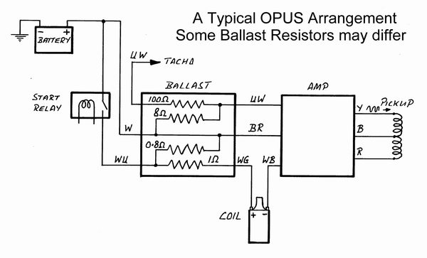
Lucas OPUS.
One of the first fully electronic systems to become established was Lucas OPUS which was initially proven in racing at Formula One level and then entered production on the Jaguar V12 - an engine for which contact breakers would have been totally impractical. The name is derived from the method of operation, i.e. Oscillating Pick-Up System.
The amplifier contains an oscillator circuit with an output frequency of 600khz, this being transmitted through one winding of the pickup, which is actually a transformer with windings on an open ended E shaped ferrite core. The resistance of these windings should be nominally 2.5 Ohms (centre to red wire) and 0.9 Ohm (centre to black wire).
A moulded nylon rotor is mounted on the distributor shaft and carries ferrite rods, spaced one per cylinder axially around the circumference so that they can periodically bridge the upper two legs of the core. As each rod passes the pickup the magnetic circuit of the upper part is completed, communicating the 600khz signal to the secondary pickup winding and back to the amplifier which turns off the current through the coil to generate an H.T. spark in the normal way. The constant 600khz signal to the pickup and the returning signal, with changes of amplitude as the ferrite rods pass the pickup, can be clearly observed with an oscilloscope. The ferrite rods only align across the upper half of the pickup E core, which is somewhat fragile and must be handled with care. An interesting effect is that if the ignition is turned on with the engine not running and one of the ferrite rods happens to be aligned with the pickup the oscillator signal will be transmitted continuously to the output transistor causing a weak HT spark train to be generated at the oscillator frequency. This phenomenon can be a fair, though not infallible, indication that the system is functioning properly. Whenever no ferrite rod is in proximity to the pickup the output transistor will be switched on and current will flow through the coil.
Because of this the circuit still requires a ballast resistor to limit current through the coil, which typically has a primary resistance of about 1 ohm, but the maximum spark rate capability is about double that of a contact breaker system. For the V12, as with most applications, the OPUS amplifier came inside a cast metal box with fins on top although it came built into the distributor for the early EFI 4.2 Jaguar, a configuration which proved troublesome.
There were a number of variations in the OPUS system as applied to the V12. A high energy (i.e. low resistance) coil was introduced during 1978 along with a an uprated amplifier designed to handle the increased current. There were also variations in the ballast resistor arrangements and a long lead amplifier was introduced latterly to enable the amplifier to be remotely mounted because engine heat had been thought to be a cause of unreliability. There is nothing to prevent the leads being extended on the earlier amplifiers for the same purpose, despite uninformed claims to the contrary.
Timing Settings.
All are with no vacuum applied. Static figure is target for initial setting up. Timing should then be set to higher speed figure approximating to the peak torque regime.
| V12 E type (CD carbs) 9:1 compression. | |
| 750 r.p.m. (static) | 12 degrees BTDC |
| 3500 r.p.m. | 31 degrees BTDC |
| Bosch Lucas EFI, 9:1 compression, 1975-80. | |
| 750 r.p.m. (static) | 10 degrees BTDC |
| 3000 r.p.m. | 29 degrees BTDC |
| Lucas 6CU EFI, pre-HE 10:1 compression, 1980-81. | |
| 750 r.p.m. (static) | 5 degrees BTDC |
| 3000 r.p.m. | 24 degrees BTDC |
The slightly more advance applied to the V12 E type reflects the fuel rating of 98 RON (rather than 97 RON quoted for later 9:1 engines) and also the breathing limitations of the CD carburettor arrangement.
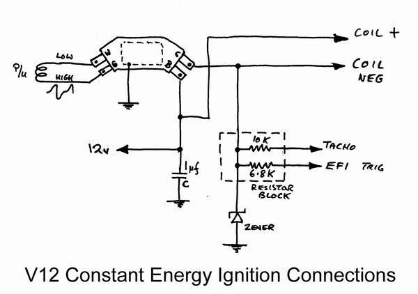
Lucas Constant Energy Ignition.
In its original form the constant energy ignition system used a Fairchild SH 4240 control package which contained a high voltage Darlington power transistor and control circuitry based around a dedicated integrated circuit. Heat produced by the transistor was dissipated by mounting it on a substrate of beryllia (beryllium oxide), which is toxic so these units should never be broken open or crushed.
The trigger input used in all Jaguar applications is the simple inductive pick-up, essentially a magnetically sensitive coil which creates an output voltage when pole pieces move past, these being in the form of individual teeth for each cylinder disposed around a rotor. The winding resistance is likely to be about 3.3K Ohms, but is quoted as being from 2.2K to 4.8K, which seems a bit hazy really.
The waveform produced is a sort of distorted sine wave, rising to a peak positive value then abruptly swinging negative as the pole piece moves through the point of exact alignment (see diagram). Fortuitously this provides a very reliable switching point with which to trigger the ignition event. The drawback is that a sine wave type of signal spends the same amount of time in the negative phase, as in the positive, so even if the switching were to take place at the zero crossing point the maximum on time for the coil could never exceed half of a cycle. To complicate things further if, at low speeds, the coil were turned on for as long as half the cycle either the coil or the module would then have to dissipate a lot of heat. The clever thing about the constant energy module is that it deals with this conundrum rather well by biasing the trigger signal so that it lifts with rising speed. The switching-on point therefore can be quite late (in terms of rotation) at low speeds and then advances forward as speed increases. With the aid of an oscilloscope this can be seen as an upward distortion of the waveform (see diagram) with rising speed. A consequence of shifting the waveform in this way is that the firing point retards very slightly - barely 1 degree or so - with rising speed because of the downward signal slope at this point. This is of no concern because it amounts to less than the tolerance spread of a typical advance mechanism and can be allowed for in the timing setting.
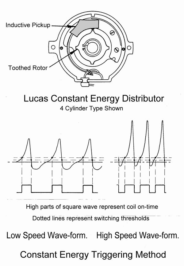
The threshold where switching takes place is about 1 volt or thereabouts, so there is a slight problem in that at low speeds the voltage signal from the pickup only rises rather gradually, so does not provide a very positive turn-on point. The solution is to use a standard circuit configuration called a "Schmitt trigger" which, once triggered, requires the signal to fall significantly before switching off again, so a positive switching action is always obtained, rather like an over-centre mechanical linkage.
First appearing on the XJ6 4.2 EFI engine, where it was a clear improvement over the previous troublesome OPUS arrangement, the constant energy system arrived on the V12 with the introduction of the HE engine. The 12 cylinder spark rate and abnormally high 12.5:1 compression ratio of the original HE demanded an ignition system capable of building up heavy coil primary current exceptionally quickly. The solution arrived at was cleverly practical, a second coil with the HT turret sealed off was connected in parallel with the first, thereby doubling the current flow and halving the time needed to reach the required energy level. When a suitable single coil eventually became available from Ducellier, having 0.5 ohms primary resistance, this was adopted and the second parallel coil was discontinued.
The constant energy module is contained in a heat sink case with a Zener protection diode, a couple of limiting resistors and a capacitor. In some operating regimes, idling in particular, the module has to limit coil current and needs to dissipate quite a lot of heat so it must never be run without being mounted within the heat sink case.
Timing Settings.
With no vacuum applied. Static figure is target for initial setting up. Timing should then be set to higher speed figure approximating to the peak torque regime.
| HE V12 XJ-S 1981-88 & HE Saloon 1981-91. | |
| 750 r.p.m. (static) | 0 degrees BTDC |
| 3000 r.p.m. | 18 degrees BTDC |
Marelli digital ignition
At the end of 1988 the V12 at last moved on from its rather primitive and complicated centrifugal and vacuum advance ignition detailed elsewhere on this site, to a programmed microprocessor system made by Marelli. Not surprisingly, having to deal with 12 cylinders, this is quite complicated as well, but at least it does away with the awful tangle of solenoids, valves, and vacuum pipes of its predecessor.
The most distinctive feature is the unique arrangement of twin coils feeding to a pair of centre posts on the distributor, within which a two level rotor arm directs the HT to the respective cylinders. The 12 terminal posts form two tiers inside the cap to align alternately with one end or other of the rotor arm to direct the spark, the upper tier relating to the RH (A) bank of cylinders. The arrangement permits the distributor to be made more compact without risk of flash-over between adjacent terminals. The current to the two coils is controlled by a pair of constant energy modules mounted above the radiator, each module/coil combination dealing with one bank of cylinders.
The ECU is located in the passenger foot-well (XJ-S) or below the glove box (saloon) and has a vacuum pipe connection to sense load according to manifold pressure. Electrical connections are made via a 25 pin connector.
As an emission control feature on non-catalyst cars a solenoid valve and temperature switch inhibit the full vacuum signal below 40 degrees C and instead provide a throttle edge signal which is ineffective at idle. There is also a delay valve in this vacuum route to slow the rate at which advance is applied during this condition.
Triggering is from a three toothed rotor mounted on the crank pulley, providing a register signal via pin 1, for each A bank cylinder at 8 degrees ATDC. B bank firing points are then calculated via the speed signal, which is taken from the flywheel teeth to pin 16. Both pickups are of inductive type and the air gap setting is quoted as a rather unfussy 0.018 to 0.042 inches (0.45 - 1.0 mm).
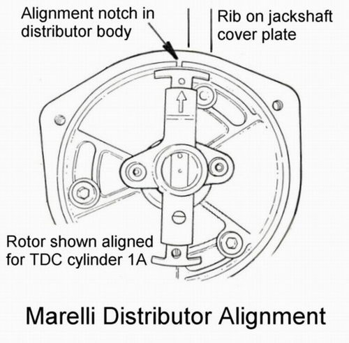
Obviously there is no advance retard mechanism in the distributor however it is critical to have it in correct alignment so that spark gaps between the rotor tips and terminal posts do not become too large. With cylinder 1A at TDC the rotor arrow should align with the notch in the distributor body and both should be in approximate line with the rib on top of the jackshaft cover plate. This important point does not seem to be mentioned in the factory workshop manual.
There is a conventional coolant temperature sensor behind A bank thermostat providing correction in the usual way. 5.3 litre engines have an air temperature switch attached to A bank air filter box to activate a retard factor when air temperature exceeds 75 C as a means of avoiding detonation at elevated air temperatures.
A switch attached to B bank throttle linkage signals the ECU when the throttles are closed. In this condition the timing is governed according to engine speed and coolant temperature alone, the vacuum signal being ignored in order to achieve the most stable running condition.
There are two small electrical sockets just behind B bank throttle, a three way for a diagnostic link to the JDS system, the other a two way, also identifiable by having a yellow wire, in which a link can be inserted for octane map selection. Link in = 95 RON fuel, link out = 91 RON. There is obviously a performance penalty in the latter state.
A slightly odd feature is that the tachometer signal is taken from only one coil and therefore corresponds to a 6 cylinder engine but the tachometer is, of course, calibrated accordingly.
The triggering method for the separate injection ECU differs from the earlier constant energy system in which the signal was derived from the coil primary waveform. With Marelli ignition the trigger function is provided by the ignition ECU in the form of a square wave pulse so the input sensitivity of the fuel ECU was altered to suit. This means that fuel ECUs for Marelli equipped cars cannot be interchanged satisfactorily with those having Lucas ignition although they may well start and run.
6 Litre Changes.
For the introduction of the 6 litre engine in 1993 the coolant sensor was deleted and was replaced by an air temperature sensor to provide a wider ranging correction for detonation avoidance instead of the two state control formerly provided by the temperature switch.
A retard request link-up was introduced to work with the four speed electronically controlled transmission. During shifts the timing is briefly retarded to improve shift refinement. Retard is also activated at wide throttle openings (vacuum sensed) in reverse gear.
Marelli Failures.
There have been lots of stories about the perils of Marelli ignition failures. I was once told that it was a major crisis and that cars were "burning to the ground on a daily basis". If this were true then it would indeed be a problem which has to be taken seriously. Yet despite many stories and rumours somehow it is hard to find any solid evidence to substantiate them and one has to wonder if there really is such a thing as the "Marelli problem".
There is no doubt that the two level rotor arm can be a source of trouble - the insulation breaks down under the upper conductor allowing the HT to track to ground via the distributor spindle. The cap also can degrade. The reason is not hard to find. A consequence of programmed ignition advance is that the gap from the rotor tip to the HT posts can at times be quite wide and this creates enormous HT stress across the insulation - more than would be found in a centrifugal advance system which inherently tends to keep the rotor tip reasonably well aligned with the posts. It is not unknown for programmed ignition systems to have a centrifugal advance mechanism in the distributor for exactly this purpose - the Jaguar 2.9 XJ40 being one example. Nevertheless V12 rotor failures are by no means a problem of epidemic proportions in Europe.
It is possible that there may be a different usage pattern in the USA that could aggravate HT stress failures in Marelli rotor arms. Prolonged freeway cruising, for instance, would involve a part load condition with maximum advance which may well mean a more prolonged wide gap situation inside the rotor. This is why correct alignment of the distributor is critical and there may even be some merit in turning the distributor a few (i.e. no more than 2 or 3) degrees anti-clockwise to reduce the gap slightly at full advance.
Where a car has a history of rotor failures, one might wonder perhaps, if, rather than condemning the system, there might be something wrong on the car aggravating the condition. Possibilities are:- a badly aligned distributor; faulty HT lead; disconnected or fouled injectors.
Failure of the upper rotor has the unfortunate effect of disabling ignition to A bank and in the right circumstances the continued passage of fuel and air onto the hot catalyst will quickly cause it to overheat and melt out. This might sound like damning evidence of a problem, but in reality catalyst burn-outs are quite common events that rarely cause trouble. It has happened to me (not in a Jaguar) and I didn't even know about it. It only needs one misfiring cylinder and the ensuing charge of unburnt fuel and air will soon wreck any catalyst. When I worked at Jaguar I can remember having to provoke such situations deliberately as part of the Japanese Heat Damage Test. It doesn't take much.
It is fairly well known that VW/Audi have had an epidemic of coil (on plug) failures on all models in recent times. Every such failure is likely to cause a catalyst to melt out yet if there has been any outcry about "burnt out beetles" it has somehow missed my attention.
The only difference with an entire cylinder bank failing is that it will be over so much more rapidly and therefore probably less of a threat. I wonder how many of the allegedly burnt out V12s had not had the front plugs changed in years, or how much leaking oil had coagulated down the side of the engine beforehand just waiting to be ignited? And how long had the driver ignored a slight misfire?
I made my own enquiries into the "Marelli problem" and came to the following conclusions:-
Contrary to some views Jaguar have a good record on dealing with aftermarket problems as illustrated by their responsible way of dealing with Nikasil liner problems on the V8. A recall was instigated on the V12 in 1992 to rectify a potential fire hazard. It involved the king lead from B Bank promoting ozone degradation of the closely adjacent 4A injector hose. Then it was found that on the 6 litre XJ-S the bonnet lining could contact and apply pressure to the wiring to A Bank ignition amplifier and cause a misfire or even total cut on that bank accompanied by failure of the tachometer signal. The service action bulletin, describing how to relocate the amplifier, comments that damage may occur to the RH catalyst if the car continues in use. Engineers at Jaguar do not seem to be aware of any other problem.
Enquiries with Jaguar dealerships and non-franchised specialists in the UK and the USA always produced answers on the lines of "yes they sometimes fail and occasionally a catalyst melts out but it isn't a serious problem". There was an inference, not from Jaguar, that most cars that suffered had an indifferent maintenance history. I also made enquiries about the number of Marelli rotor arms sold. It isn't that many. Our local Jaguar dealership, in a Jaguar rich area, sells about 1 a year and that's in total through workshop and counter!
It has been claimed that fire investigators aren't looking for the condition so aren't picking up on it but it is the investigators who actually see burnt out cars and assess the evidence. Anyone else's opinion can only be speculation. There are lots of reasons why cars catch fire but it seems that any fire on a V12 Jaguar is immediately seized on by some as another "Marelli burn out".
The EPA are notoriously quick to act on these sort of problems yet not a word has been said about the V12 Jaguar. Either their customary alertness has been put on hold or there isn't much there to attract their attention.
A couple of years or so back there was a well-meaning guy who tried to start a sort of "Marelli victim action movement" on the XJ-S lovers forum, where these stories have been more rife than anywhere. He invited all those who had suffered catastrophic Marelli failures to provide details of their experiences with a view to making a joint legal challenge. Result - just 4 respondents, only one of which had involved a fire of any sort.
In the absence of any convincing evidence one has to conclude that the "Marelli problem", if it exists at all, is a minor issue. Surely it is now time to stop all the scare-mongering.
A note about measuring low resistances such as coil primary windings.
It is easy to forget that when measuring very low resistances that the resistance of the test leads must always be taken into account. It is essential to measure the lead resistance, by joining the probe tips together, before attempting to measure a suspect component. A typical figure would be about 0.3 to 0.4 Ohm so a large error would be involved when measuring a low resistance coil unless this were to be deducted. Modern coil-on-plug coils may have a resistance of as little as 0.1 Ohm so the test lead effect then completely swamps the result.
In any case low cost meters may not be very accurate at measuring at such levels. For better accuracy we sometimes revert to fundamentals and measure the current flow at some low voltage from a regulated power supply and then calculate the resistance via Ohm's law. As an example, applying 1 volt to the primary winding of the V12 HE Ducelier coil draws a current of almost exactly 2 amps.
From Ohm's law:- R = V/I (R = Ohms, V = Volts, I = Amps current)
R = 1/2 = 0.5
The coil primary resistance is therefore 0.5 Ohm.
A note about instruments for diagnostics.
A lot of people still drone on about how to diagnose ignition faults by measuring voltages and resistances with a multimeter. Really such methods are very much second best to doing things properly. In the days when more comprehensive instruments were much more expensive there was perhaps some excuse but small hand-held oscilloscopes can now be purchased for not much over Ł100. A 'scope is so useful that its purchase would be justified many times over by any enthusiast who has to tinker about with car electrics. Looking at what happens to the wave-forms in an ignition system, or at the output from any sort of trigger pickup, is so much more informative that one has to wonder why anyone would want to try to sort things out any other way.
Email aj6engineering@ntlworld.com, Tel/Fax:- 0044 (0)1625 573556