| Menu |
| Homepage |
| NEW & REVISED BOOK! |
| Personal intro |
| Philosophy |
| Intro technics |
| FAQ |
| Exhaust systems |
| Exhaust overview |
| E-type |
| XJ Saloon S1,2,3 |
| XJ40 (AJ6&V12)/X300 |
| XJS |
| XK8/XJ8 |
| TT exhaust explained |
| The Jaguar V12 |
| V12 Performance |
| Stretching the V12 |
| E-type EFI conversion |
| D Jetronic |
| Lucas EFI |
| Vacuum advance |
| Ignition systems |
| V12 throttle linkage |
| Article: V12 Engine |
| V12 Archives |
| The Jaguar AJ6 |
| AJ6 Performance |
| 3.6 Richness |
| AJ6 fault codes |
| AJ6 Archives |
| The Jaguar XK |
| XK Performance |
| Article: XK Engine |
| Article: 4.2 EFI |
| The Jaguar V8 |
| V8 Performance |
| AJ6 Superchargers |
| Superchargers |
| Supercharging article |
| Suspension & Brakes |
| Miscellaneous bits |
| Glossary |
| Prices & ordering |
aj6engineering@ntlworld.com
Updated August 2016
Visitors:
82032826
|
|
A brief account of ECU evolution.
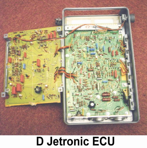
The first generation of Fuel Injection ECUs in the late 1960s and 70s used analogue techniques employing resistors and timer circuits to produce rather basic fueling laws which were 'best matched' to the engine requirements. These systems were a significant advance over carburettors for reducing exhaust emissions with the primitive oxidation catalyst technology of the time. The Lucas/Bosch D Jetronic system found on the early (1976-80) V12 Jaguar was of this type and a full description of its working methods can be found in the V12 section of this website.
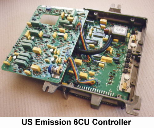
By the 1980s digital technology had appeared and more precise fueling control became possible. A custom chip contained a block of data relating to speed and load with a clock and counter to generate the injector pulses. Corrections for coolant and air temperature and other secondary factors were dealt with by analogue circuitry which modulated the clock frequency. Some of these systems were able to control fueling very accurately by using feedback from an exhaust oxygen (Lambda) censor for use with more effective three-way catalysts. Such digital EFI systems were used on the Jaguar V12 from 1980 - 86, the 3.6 from 1983 - 87 and on the Rover V8 in the Vitesse and then the Range Rover until 1989. Again the V12 section has a full description of digital systems.
Microprocessors soon ousted digital systems because of their much greater ability to accurately optimise every facet of engine control including ignition timing, idle speed and evaporative emissions, a collective arrangement known as engine management. The more advanced systems have what is called 'adaptive memory' which provides the ability to learn the characteristics of an individual engine and adjust the program to suit it. This sort of device spawned 'chip tuning' where an Eprom chip containing the operating data would be swapped for one that hopefully gave increased performance. These techniques are described in more detail in the V12 section.
Ever tighter exhaust emission legislation necessitated self diagnosis and limp home capability - impossible with the earlier systems but relatively easy to accomplish with microprocessors, the programs for which rapidly grew in size as more features were added. In fact one of the great attractions of microprocessors is that many embellishments can be added just by changing the program without disturbing tried and tested hardware.
Most manufacturers moved onto 8 bit microprocessor based systems during the mid 1980s and by the end of the decade the last of the digital systems were superseded. The V12 Jaguar went to micro EFI in 1986. The Rover V8 in 1989, but the XJ40 saloon was introduced with full engine management in 1986, the same system replacing digital EFI on the 3.6 XJS the following year.
Modern systems introduced through the 1990s became very complex with powerful 32 bit processors to deal with the demands of OBD2 (the On-Board Diagnostics protocol), vehicle security and links with other systems in the car. Reprogramming such devices requires a very high level of expertise and is getting beyond the realms of 'chip tuning'.
Techniques for testing ECUs.
The first essential for carrying out this sort of work is a bench top rig to simulate conditions in the vehicle. Such equipment is not commercially available so has to made for the purpose as ours was. Standard laboratory instruments such as an oscilloscope, a variable power supply, a multimeter, a pulse timer and a waveform generator are also needed in addition to the purpose made items. Barometric pressure is a perpetual variable that has to be taken into account during any test procedure in addition to any simulated engine vacuum load signal. More specialised equipment such as a computer link or an Eprom programmer / emulator is necessary to develop changes of program data in later systems.
It is important that the right sort of signals are created to reproduce exactly what happens on the car and for many EFI systems this entails constructing a complete ignition system and spark gap to produce a representative trigger signal. This introduces problems with HT interference which must be screened so that false signals are not introduced. If one is checking for a fault then it is essential that the test equipment does not generate one that otherwise would not be present. It may sound easy but some ECUs are very fussy about the trigger wave-form and will misbehave even if the spark gap on the rig is wrong.
Another critical input is that for Lambda feedback which needs a simulated signal with very fine adjustment to check the corrections applied to the injector pulses.
Sometimes a fault will be obvious right away but many will be intermittent and might only become apparent after prolonged testing, while exposed to temperature cycling and vibration. For this reason, and because changes are often introduced during manufacture, it is not acceptable to pronounce an ECU good or faulty on the basis of a quick function test as some people seem to think. When a fault is confirmed (ECUs are condemned all too readily) a failed component can be identified and changed but any bad soldered joints (dry joints) can be very elusive. Some repairers just blob extra solder on all the joints but the only really satisfactory solution is to de-lacquer the board and completely de-solder it and start again with all the joints remade with fresh solder and then relacquered. Such a repair should give years of reliable service.
Airflow meter calibration.
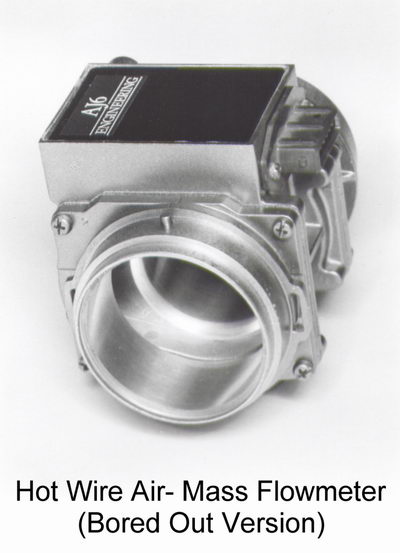
Closely associated with ECU work is the testing of airflow meters. For the hot wire type we use an airflow rig to measure the signal voltage against standard rates of airflow for checking and calibration purposes. The signal output from the earlier flap type is very non-linear so we find the most accurate test method is to run it as part of a benchtop EFI system and measure the injector pulse width from the ECU for given rates of air flow.
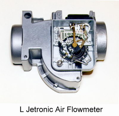
These techniques make it possible for us to modify these units to reduce the resistance they offer to airflow into the engine and re-calibrate them to provide the appropriate signal to run the engine as normal. We bore out the hot wire type and reduce the spring resistance of the flap type as part of our performance conversions. The flap type must then be used with a matched ECU calibrated to work with the different load signal.
What else do we do to ECUs.
As we already have bench test rigs for repair work we can easily measure the effect of any changes and develop new specifications to improve drivability and to complement induction or exhaust system changes based on dynamometer experiments. If we know from testing what changes are required to suit a particular engine modification we can develop the necessary ECU changes on the bench top, either of circuitry or program, according to type to meet the specification. Usually this work will be refined in subsequent testing on the road or dynamometer. Our involvement with the Jaguar V12 engine has continued for so many years that we have built up a wealth of data to enable us to modify an ECU to suit almost any change to that engine virtually off-the-shelf.
We reshape the fueling laws of early analogue ECUs (Bosch D & L Jetronic) by circuitry or component changes and we employ similar techniques to modify the first generation digital types (Lucas 4CU, 6CU, 8CU) that followed.
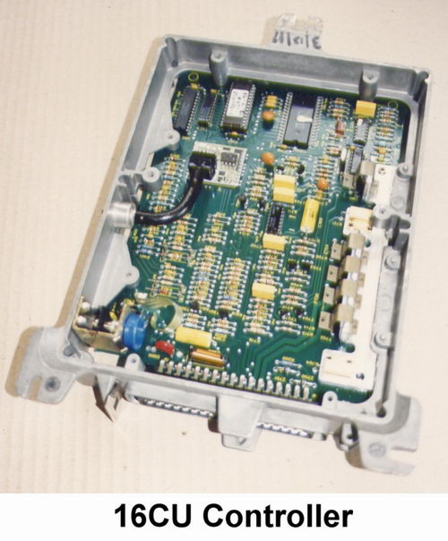
For the microprocessor systems, like Lucas 16CU and its successors, we alter the map data in the program although in some cases we make minor circuit changes as well, usually to change the sensitivity of a signal input to suit the revised conditions. In some cases we provide a means of adjusting the fueling on the car, which can be useful for specially modified engines or those to be used for racing. We also have other solutions to the problem of adapting engine management systems to run with modified engines.
Email aj6engineering@ntlworld.com, Tel/Fax:- 0044 (0)1625 573556