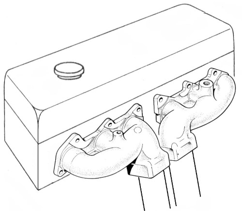
Most enthusiasts will be familiar with the cast exhaust manifolds typical of many production engines, including all Jaguar 6 and 12 cylinder engines, shown in the illustration. Each such manifold serves three cylinders at one end or the other of the engine.
It is seems intuitive that an arrangement with exhaust ports coupled so closely together must suffer interference between the exhaust actions of the cylinders.
Similarly the tubular manifold system in the next illustration would seem to be so much better because the exhaust discharges of the cylinders are nicely separated by the branches. The Jaguar D Type was probably a major inspiration for the popularity of this layout yet it comes from a time when the potential of exhaust dynamics was barely recognised.
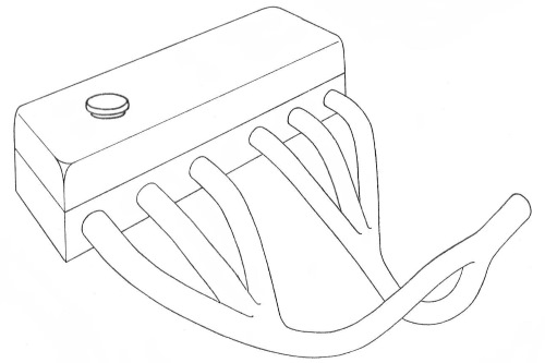
Despite its superficial attractions the arrangement actually has very little merit when subjected to performance testing on a dynamometer.
In reality, each group of three cylinders fire at equally spaced intervals that do not overlap so each cylinder in the group can complete its own exhaust cycle without any conflict with the others.
Even with longer duration cams the exhaust pressure cycles of the cylinders still do not overlap in the effective operating speed. There may be some interference at low speeds but if low speed performance is important then long duration cams would be a bad choice.
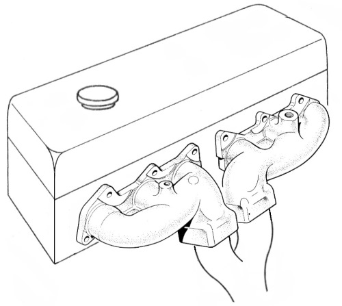
Of course, this is unlike the situation with four cylinders grouped in the same way where overlap of exhaust cycles would certainly take place.
At this point we need to consider what really happens in an effective extractor exhaust system. Separation, gas column inertia, and back pressure, are all terms that get bandied about in this context but none of these are anywhere near as important as the pulse activity that does the real work.
Surprisingly, back pressure is one of the least important considerations unless the system is exceptionally restrictive. If one removed the tail trim from a typical road car and replaced it with a cap having just a 0.5” diameter hole, in most cases the loss of performance would be hardly noticeable below about 3000 r.p.m.
When the exhaust valve starts to open, pressurised gases begin to discharge at sonic velocity into the port thereby generating a positive pressure pulse which travels down the system at the speed of sound. When such a pulse reaches a point where there is an increase of volume which allows it to expand, such as the pipe end or at a junction with another pipe, the expansion of the pulse creates a negative pressure (rarefied) pulse which travels back towards the cylinder, again at the speed of sound.
If this negative pulse arrives at the exhaust valve just before it closes, it passes into the cylinder causing a reduction of pressure therein, just before the next induction cycle commences, and the lowered pressure in the cylinder will augment the deep suction phase at the start of the induction process and increase its effectiveness. In this way, well-timed pulse action taking place in the exhaust system actually contributes to the mass of charge inhaled by the induction system. Note that the critical pulse action all takes place within the total opening period of the exhaust valve.
Of course it is all a bit more complicated than that but it is the basis on which efficient engine systems operate and when combined with a similar pulse activity in the induction system makes it possible for modern racing engines to achieve volumetric efficiencies as high as 140%. To put this in another way, it enables the engine to consume 40% more air than would be expected from the swept volume of all of its pistons.
It will be apparent that the pulse actions must be synchronised to the engine and the main factor here is the distance from the exhaust valve to the reflection point at the end of the pipe, so the length of the pipe determines the speed range at which it will be effective. Because the pulse action takes place within the valve opening period it is possible for three adjacent cylinders with equal firing intervals to carry out this process through a shared pipe.
The two pipes from 6 cylinders can be merged into one at the extremities to feed into a common tail pipe and the change of volume at the junction would still provide the expansion space to create the required negative return pulses.
The pulse activity can continue even beyond the junction into the tail pipe with negative pulses reflecting from the pipe end timed to augment the main pulse action.
Returning to the classic short branch tubular manifold it will now become more obvious why this arrangement cannot work very well. Any outgoing positive pulse will be able to expand at the three-way junction and send a negative pulse back prematurely whilst some of the outgoing pulse energy is diverted up the other two branches where it is reflected back from the closed valves. The required reflected negative pulse from the merge joint between the two groups of three will not only be weakened by the energy already lost, it will also be divided between the three pipes as it returns. There will also be complex reflections from the individual pipes re-entering the system at times when they cannot have any useful effect.
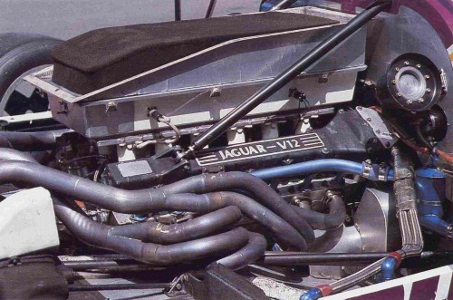
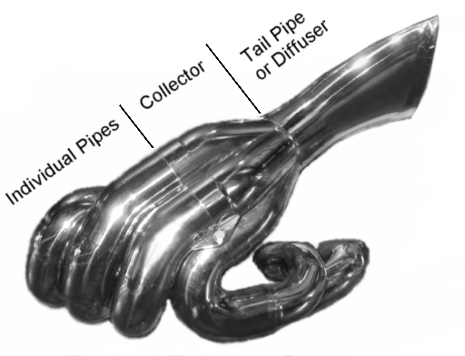
The situation is quite different if the individual pipes are all of such length that they can deliver the negative pulses at the correct time, but there is rarely space in an engine bay for all the tubular mass that this would involve. The system will also be heavy and a considerable source of radiant heat. Of course, the critical pipe lengths for a high speed racing engine would be shorter than most road cars which helps to alleviate the bulk issues but even so the individual pipes used for the XJR-9 system in the photo are somewhere near 36 inches in length.
The diameter of the pipes can also be important but not in the simplistic ‘bigger equals better’ way that some people imagine. The idea that enlarging the pipe sizes will somehow release more power is rarely true of modern cars unless the engine has been significantly modified and even then any benefit will only be at the top of the speed range, whilst performance may actually be reduced at lower speeds because of the reduced gas velocity. The engine will probably sound a bit more ‘throaty’ which may be reason enough for some people.
Of course large pipes might look impressive but there are plenty of examples of high performance and racing cars which have been successful with relatively modestly sized pipework.
Large V8s are exceptions that can benefit from larger pipes and also crossovers because of the irregular flow produced by the uneven firing order along the two banks of cylinders.
Another question that sometimes arises is about possible restriction caused by having curved pipes threading through the suspension, typical of many Jaguars. In fact exhaust gases are highly energetic and have no difficulty navigating through even the tightest of bends as can be readily seen from the closely packed exhaust systems of modern F1 cars.
Silencing and Sounds
All of our systems have straight-through silencers which provide reasonable silencing with minimal restriction. The TT Super Sport for the V12 E type is perhaps an exuberant exception but even that can be tamed with the optional underfloor silencers.
I am sometimes asked if I can provide a sound clip of one of our exhaust systems and I know lots of people do it but I believe that sound recordings are more likely to mislead than provide any reliable guidance.
The reason I say that is because many years ago I had some involvement with industrial acoustics and one of the things I learnt was that the background and ambient conditions have a serious influence on the result when recording or measuring sound. It can be likened to trying to take photographs in a hall full of random flashing lights and wonky mirrors. That is why musicians and entertainers generally make recordings in studios and why acoustic analysis is often conducted inside anechoic chambers.
Only if a recording is taken in a controlled environment can it ever be representative and that isn't really practical in these instances. Consider how often car and engine noises in films and TV programs sound nothing like the real thing – and they have sound engineers with high level recording equipment who still cannot get it right.
Copyright of Roger Bywater and AJ6 Engineering - 2015.