| Menu |
| Homepage |
| NEW & REVISED BOOK! |
| Personal intro |
| Philosophy |
| Intro technics |
| FAQ |
| Exhaust systems |
| Exhaust overview |
| E-type |
| XJ Saloon S1,2,3 |
| XJ40 (AJ6&V12)/X300 |
| XJS |
| XK8/XJ8 |
| TT exhaust explained |
| The Jaguar V12 |
| V12 Performance |
| Stretching the V12 |
| E-type EFI conversion |
| D Jetronic |
| Lucas EFI |
| Ignition systems |
| V12 throttle linkage |
| Article: V12 Engine |
| V12 Archives |
| The Jaguar AJ6 |
| AJ6 Performance |
| 3.6 Richness |
| AJ6 fault codes |
| AJ6 Archives |
| The Jaguar XK |
| XK Performance |
| Article: XK Engine |
| Article: 4.2 EFI |
| The Jaguar V8 |
| V8 Performance |
| AJ6 Superchargers |
| Superchargers |
| Supercharging article |
| Suspension & Brakes |
| ECU repairs |
| Miscellaneous bits |
| Glossary |
| Prices & ordering |
aj6engineering@ntlworld.com
Updated August 2016
Visitors:
82034274
|
|
Based on Articles by Roger Bywater for the XJ-S Bulletin
1. The reasoning behind the complex vacuum advance system used on the HE V12 .
The vacuum advance system used on the HE V12 from 1981-88 (XJ-S) and 1981-92 (S3 Saloon) is particularly intricate. It is worth considering the history and development behind it in order to understand why such complication is necessary.
The HE V12 was the result of a concentrated (one might say desperate) effort by Jaguar to overcome the V12's appalling thirst for fuel. The V12's future, and indeed that of Jaguar itself, was hanging on this very issue as the 1970s drew to a close. Circumstances demanded a very substantial improvement yet the serious financial difficulties of British Leyland meant there was hardly any budget to work with. A new engine was completely out of the question - experiments which eventually would lead to the AJ6 engine were in an embryonic state yet to drop the V12 and fall back on the ageing XK was clearly not a viable alternative. The saloon could hang on for a few years with the XK but the flagship XJS had been designed around the V12 and would have become a dead duck. The V12 HAD to be improved dramatically or Jaguar would go bust - it was as simple as that!
A lot of alternatives were looked at and the single cylinder test bed was in almost constant use. I personally had minor involvement in some experiments - various stratified charge pre-chambers were tried without showing any great promise, and a small bore inlet port / high turbulence configuration (the original V12 was known to suffer charge stagnation at part throttle) showed some part throttle improvement but severely limited maximum power. That clearly had no future because above all a 5.3 litre V12 needs to offer good full throttle performance to be credible. A project I had responsibility for was a "split 12", as we called it, which ran on 6 cylinders in light load conditions and brought in all twelve on demand. A complex arrangement of throttles and actuators provided acceptable drivability and the economy gains in moderate speed steady state cruises were quite considerable but there was no benefit above about 80 m.p.h. and the system was very sensitive to driver technique. There would also have been considerable difficulties to overcome in respect of exhaust emissions.
Around the same time a Swiss engineer called Michael May was trying to interest the motor industry in a new combustion chamber design which combined lean burn and high turbulence techniques to achieve high fuel efficiency at abnormally high compression ratios. A number of manufacturers looked at it and some even ran prototypes but generally they concluded that the gains were not substantial enough to take it further. It may well be that most were under less pressure than Jaguar and were in the happy position of being able to think long term and rate Michael May's work against other more fundamental future developments such as the four valve per cylinder arrangement which we now take almost for granted.
The V12 Jaguar was the exception. Here was a big lazy engine with indifferent light throttle efficiency exactly in the operating regime in which the May design excelled. They were made for each other.
Harry Mundy, Jaguar's Chief Engineer over Power Units, recognised that this was a chance to haul the V12 back from the dead and after some single cylinder work to iron out the details to suit the V12 bore and stroke, a slant six (one bank of a V12) prototype started running in a car. This ran initially at around 14.5:1 compression and I remember one day hearing it demonstrate a horrific bout of "pinking" as it was driven past. Eventually the compression ratio was settled at a more reasonable 12.5:1 (11.5:1 for unleaded fuel in the USA) but the high cylinder pressures demanded a very powerful ignition system with abnormally wide ranging ignition timing to exploit the new combustion chamber to best advantage.
In fact a key element of exploiting the May design was balancing ignition advance and compression ratio. Full throttle performance was never the issue because raising compression required the ignition to be retarded accordingly so fuel economy was hardly different from the earlier "flat head" V12, although power was on a par with the best pre-HE, the short lived 10:1 compression engine of 1980 delivering around 300 b.h.p. in European trim. This was an important factor because the power and torque advantage over the earlier 9:1 compression V12 made possible the use of higher gearing via a 2.88 axle ratio to further improve economy during cruise where the real gains were to be made. Here there was a clear trade-off between compression ratio and economy. The higher the compression the lower would be the best economy speed. In settling on 12.5:1 Jaguar pitched for best economy at motorway speeds below 100 m.p.h. which was what most drivers would value. It now remained to control ignition timing to suit the unusual needs of the engine.
At full throttle the high compression ratio would not tolerate much ignition advance yet at part throttle cruise a substantial amount of advance was necessary to light the slower burning weak mixtures needed for best economy. Then at idle it was necessary to limit the amount of advance to maintain acceptable idle quality. Even so an HE was never as smooth at idle as it's predecessors had been. A further complication was that by increasing combustion efficiency the heat losses to coolant and exhaust were reduced causing prolonged warm up times and emission problems because of slow catalyst light-off on cars which were so equipped. It was therefore necessary to retard the ignition timing considerably following a cold start to release more heat into the system and get the 36 or so pints of coolant up to temperature.
What was needed was a modern programmed ignition system but in 1981 such things were very much in their infancy so it had to be done with the existing technology of valves, restrictors, solenoids and the like. This was a considerable challenge because the whole concept of the HE was heavily dependent on controlling the ignition timing in more complex ways than had been achieved before. Indeed the first clue that an HE has a fault in the vacuum advance system is that cruise consumption drops from about 20-22 m.p.g to around 16 m.p.g.
Now we know what the complex HE vacuum advance system is supposed to achieve and how important it is, we can look into how it all works.
2. A Cocktail of Solenoids, Valves, Switches and Pipes.
We have now explained why it is necessary for the HE V12 to be lumbered with such complexity to exploit its unique properties to achieve substantial economy gains over its predecessor. It is important to remember that the 5-15-12 (starts at 5" Hg, all in at 15" Hg, 12 degrees maximum advance) vacuum capsule used on the HE provides rather more advance than is normally used with other engines (e.g. 6-10-8 on pre-HE). There are a number of system variants according to the intended market and emission requirement. Emission specifications A and B are the most important so we will start with them.
Firstly, it is probably a good idea to clear away some misunderstandings that probably arise from the way the Jaguar manuals describe the workings of these systems. There are references to how the systems function above and below 4000 r.p.m. which is misleading because there is no direct speed related input to the system. It really concerns top gear conditions and the effect on the vacuum signals of the increasing engine load. The same engine speed in a lower gear would create quite a different situation with much stronger vacuum signals.
Both the coolant temperature switch and thermal vacuum valve used in the various versions have hysteresis in their action which causes a change of state at 45 degrees with rising temperature but at 38 degrees when cooling down. The official explanations do not make this clear merely referring to conditions above 45 and below 38 degrees so one might easily wonder what happens in between. In fact, a little thought will show that what happens in a start-up from say 40 degrees depends on whether the car had exceeded 45 degrees or not in the previous start.
The other notable point of confusion is that some explanations refer to the various components numerically yet the diagrams themselves are labelled alphabetically. Hardly helpful!
EMISSION A - North America. (EMISSION C is same).
The first essential here is to obtain fast catalyst 'light off' so from every start up the vacuum advance is totally inhibited for 45 seconds after starter disengagement, the resultant retarded timing being a useful tool to raise exhaust temperatures for the purpose. This function is governed by a timer relay (3) and a solenoid valve (2) which simply vents the vacuum capsule (9) to atmosphere. After the 45 second period the relay switches the solenoid valve allowing full manifold vacuum to be applied to the capsule. To ensure that in an idling condition the speed would not change abruptly at this point a solenoid air valve (6), controlled by the same circuit, permits extra air to flow into the engine from A bank air filter housing during the initial period but closes off when vacuum advance becomes active. A further solenoid valve (12) is closed for the initial period but then opens to permit a part load throttle edge vacuum from both throttles to be applied to purge the evaporative emissions canister.

An official explanation that the route via the vacuum solenoid valve (2) is somewhat restrictive allowing, if the throttle is snapped open, for advance to be held on briefly and for the engine to therefore suffer detonation seems rather tenuous. It seems more likely that a faulty solenoid valve might cause such an effect and to prevent this a dump valve (10) is added. The dump valve is a device which 'dumps' any residual vacuum at the capsule to atmosphere unless a vacuum is applied to it's lower port. Because this port is connected to an inward throttle edge tapping (1) the dump valve therefore permits vacuum to be applied to the advance capsule in all conditions except near and at full throttle when it instantly vents the upper port and the capsule to atmosphere.
In its original form that's all there was to it - but not for long.
Two problems can arise as a result of applying full vacuum advance at idle. Firstly too much advance causes idle roughness and secondly any change of engine load due to air conditioning or power steering will alter the vacuum available and lead to an unstable idle condition with a possible tendency to stall. The reach / weak corrections of a Lambda feedback system can aggravate the situation and cause a wandering idle speed.
It therefore was not long before a vacuum regulator (8) was added to the capsule pipe to limit the vacuum applied at idle to 372 millibars (about 11" Hg). The control port on the regulator was connected to an outward throttle edge tapping providing a bleed-off path for any excess vacuum at the capsule. When the throttle is opened slightly the strong throttle edge vacuum prevents this from happening so full vacuum is then applied to the capsule.
Whilst not really part of the advance system there was also a thermal vacuum valve (5) mounted on the water rail which controlled the air injection system. Below 45 C the valve permits vacuum to reach the diverter valve (11) directing secondary air from the air pump to the exhaust ports. Above this temperature the pump output is switched to atmosphere. A delay valve (7), which permits easy passage of a vacuum signal in one direction but restricts it in the reverse direction, was added to the vacuum pipe so that air injection would be maintained for a short time should the throttle be opened wide during the effective period.
EMISSION B - Europe, etc.
It seems strange to find that the vacuum advance system for the less stringent European emission requirement is more complex than that for the Federal specification but the reason is simple - it had to perform without catalysts or air injection and with higher compression.
For any start-up with coolant below 45 C a coolant temperature sensing switch (4) sets a 15 minute timer (3) which controls three solenoid valves:- a 3 way vacuum solenoid valve (1); a solenoid air valve (6); a 2 way vacuum solenoid valve (2). For the 15 minute period the 3 way vacuum solenoid valve (1) closes off the inlet manifold plenum chamber as a vacuum source so the only means of vacuum advance during this period is from the throttle edge tapping (5) via a delay valve (7) which slows the decay of vacuum with modest throttle movements. It follows that there can be no vacuum advance at idle so to maintain an acceptable idle speed the solenoid air valve (6) is held open to admit extra air from A bank air filter housing. Because of the presence of the delay valve (7) and to protect against faults a dump valve (10) is required to get rid of any vacuum advance instantly to prevent detonation if the throttle is opened wide. In the vacuum line from the 3 way vacuum solenoid valve (1) to the distributor vacuum advance capsule (9) is a vacuum regulator (8) but during the initial 15 minute period this performs no regulating function because the 2 way vacuum solenoid (2) closes off the lower port.
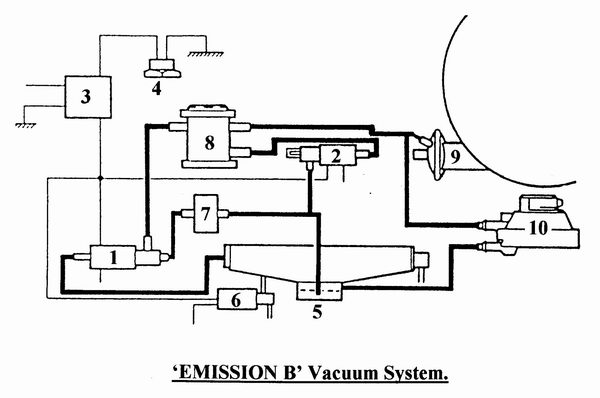
After the 15 minutes has timed out the three solenoid valves all change state so that although the solenoid air valve (6) is now closed, manifold vacuum is applied to the advance capsule so the idle speed does not change. However to prevent any idle roughness resulting from excessive advance the vacuum signal is limited by the regulator (8) to 424 millibars (about 12.5" Hg) the 2 way solenoid valve (2) now being switched over to vent any excessive vacuum to the outer throttle edge port. As with the A Emission version a slight opening of the throttle creates a strong throttle edge vacuum signal which causes the regulator to allow full manifold vacuum to reach the advance capsule (9).
For a start up from above 45 degrees the 15 minute timer would not be triggered so idle vacuum advance would be immediately active.
That's about it really. Fundamentally, the switching of the various vacuum routes is governed by temperature and timers with normal idle advance limited by a regulator allowing full manifold vacuum derived advance in part load operation but with a dump valve to eliminate any detonation tendency from residual vacuum signals.
Roger Bywater.
AJ6 Engineering
January 1999.
Email aj6engineering@ntlworld.com, Tel/Fax:- 0044 (0)1625 573556